Welcome! Use the navigation to the left to view documents.

Cautions, Notices, and Important are elements designed to prevent hazards, however, not all hazards can be foreseen. This information is placed at strategic locations within the service manual.
Caution: is used for the technician to take necessary action or not to take a prohibited action. Cautions are used to help prevent bodily injury to the technician or to the owner if the motorcycle was improperly repaired.
Notice: is used to call special attention to a necessary action or to a prohibited action. Notices are used to prevent damage to the motorcycle or prevent unnecessary repairs.
Important: is used to provide additional information or to clarify a procedure.

This symbol is located in various locations on the motorcycle to inform you that exposure to high voltage can cause shock, burns and even death.
The high voltage components on the motorcycle should be serviced by technicians with special training.
High voltage cable or wiring has an orange covering. Do not probe, tamper with, cut, or modify high voltage cable or wiring.
This manual covers the following motorcycle:
Zero FX Dual Sport
• Wire Wheels
• 21-inch Diameter Front Wheel
• 18-inch Diameter Rear Wheel
• Dual Sport Tires
Zero FXS Supermoto
• Street Tires
• Cast Wheels (17-inch Diameter)
Version 1
Caution: Brake fluid may irritate eyes and skin. In case of contact, take the following actions:
• Eye Contact-rinse thoroughly with water
• Skin Contact-wash with soap and water
• If Ingested-contact a physician immediately
Version 1
Caution: Approved safety glasses and gloves should be worn when performing this procedure to reduce the chance of personal injury.
Version 1
Caution: Test ride the motorcycle under safe conditions. Do not attempt any maneuvers that could jeopardize the motorcycles control. Failure to adhere to these precautions could lead to serious personal injury and motorcycle damage.
Version 1
Notice: Avoid spilling brake fluid onto painted or other surfaces, electrical connections, wiring, or cables. Brake fluid will damage painted or other surfaces and cause corrosion to electrical components. If any brake fluid comes in contact with painted surfaces, immediately flush the area with water. If any brake fluid comes in contact with electrical connections, wiring, or cables, use a clean shop cloth to wipe away the fluid.
Version 1
Notice: Replacement fasteners must be the correct part number for that application. Use the correct fastener in the correct location. Fasteners requiring the use of thread-locking compound are specified in the repair procedure; refer to the product manufacture for proper usage. Always use new lock nuts, lock washers and cotter pins. Do not use paints, lubricants, or corrosion inhibitors on fasteners or fastener contact surfaces unless specified in the procedure. Coatings affect fastener torque and joint clamping force and may damage the fastener
Version 1
Caution: Always perform the High Voltage Discharging procedure prior to servicing any High Voltage component or connection. Proper procedures must be followed.
Failure to follow the procedures may result in serious injury or death.
• Always verify that the high voltage has been disabled before working on or around high voltage components, wires, cables, or harnesses.
• Remove all metal objects such as rings and watches.
• Always tighten the high voltage terminal fasteners to the specified torque. Insufficient or excessive torque will cause malfunctions or damage.
• After finishing work on the high voltage system and before turning the key ON.
• Verify high voltage system integrity and that all connectors and covers are installed.
• Verify that all tools or loose components have been removed.
Caution: Exposure to high voltage can cause shock, burns, and even death. The high voltage components on the motorcycle should only be serviced by technicians familiar with the circuit/system operation. Refer to System Description and Operation.
High voltage components are identified by labels. Do not remove, open, take apart, or modify these components. High voltage cable or wiring has orange covering. Do not probe, tamper with, cut, or modify high voltage cable or wiring.
Version 1
Although unpacking the Zero motorcycle can be done by a single person, it is recommended to have a second person to help lift and remove your motorcycle from the crate base.
Wood Shipping Crate
Outer Box Cover
• Cut and remove the two metal outer box retention straps.
• Remove the screws along the crate base.
• Remove the screws along the side of the crate that has the metal clamps on it.
• Remove the metal clamps, and remove the side panel.
• Remove the remaining outer box cover.
Inner Assembly
• Carefully remove plastic cover from motorcycle.
• Locate small parts box below motorcycle and put to the side. (This box contains important documentation, owner’s manual, keys, handlebar clamps, and hardware, etc.)
• Carefully lift rear portion of the motorcycle over the swingarm standoff and off crate base.
• Carefully lift front wheel out of crate base.
• Deploy kickstand, lean motorcycle and inspect in accordance with delivery inspection sheet.
Cardboard Shipping Crate
Outer Box Cover
• Cut and remove the two outer box retention straps.
• Unscrew the stabilizer bar bolts, one on each side of outer box.
• Open box top and remove inner cardboard end reinforcement sleeves.
• Unscrew stabilizer bar from handlebar riser and remove.
• Unscrew lower crate cover retaining screws and washers.
• Lift of cut outer box away from motorcycle.
Inner Assembly
• Carefully remove plastic cover from motorcycle.
• Locate small parts box below motorcycle and put to the side. (This box contains important documentation, owner’s manual, keys).
• Remove power pack retaining frame rail.
• Remove power pack.
• Remove the tie down straps from crate base.
• Carefully lift rear portion of the motorcycle over the swingarm standoff and off crate base.
• Carefully lift front wheel out of crate base.
• Deploy kickstand (if equipped), lean motorcycle and inspect in accordance with delivery inspection sheet.
Recycling
The Zero Motorcycles shipping crate and packaging materials were designed to be completely recycled. Please cut down and recycle all cardboard, plastic, and metal materials in appropriate receptacles.
The tie down straps that accompanied your motorcycle can be reused as regular tie down straps for transporting your motorcycle.
Version 1
The latest version of the Pre-Delivery Inspection Checklist is available to your dealership through Zero Motorcycles Service Portal (Service.Zeromotorcycles.com) in the Dealer FAQ section.
Version 1
Identification Numbers
Legend
1. Identification Number
VIN Break Down
Location of Important Labels
Legend
A. VECI (Vehicle Emission Control Information) label
B. VIN label (North America) - certification label
C. VIN label (European Union) - certification label
D. Tire and loading information label
High Voltage Warning Labels
Located Near the Motor
Located on the frame if only one battery is installed.
Version 1
Tools and Equipment
Use only Zero specified tools when servicing the motorcycle. The motorcycle contains a mix of metric and standard fasteners. Use of the incorrect tool or fastener may damage the motorcycle.
All dealers should have the following:
Special Tools:
• PN 85-05665 Controller Discharge Tool

Basic Tools:
• Gloves
• Safety glasses
• Spring loaded center punch
• 2.5mm, 3mm, 4mm, 5mm, 6mm, 8mm and 10mm T, L, and socket hex wrenches
• 7 mm L Allen wrench
• T25 star driver or socket bit
• T15 tamperproof star socket
• Zip tie pulling/cutting gun
• 7mm, 8mm, 10mm, 13mm, 14mm, 15mm, 17mm, 21mm combination wrench
• Gear puller (motor sprocket)
• Rubber dead blow hammer
• Punch
• Flat and rat tail file
• Heavy duty 420 chain breaker
• Phillips and Flat head screw drivers
• 1/4" drive 1", 2”, and 3” socket extension
• 3/8" drive 1", 2", and 3" socket extension
• Needle nose pliers
• Adjustable pin spanner wrench
• 1/4" and 3/8” drive socket wrench
• Bicycle type headset press and removal tool
• Belt tension tester
• External snap ring pliers
• 7mm, 8mm, 10mm, 13mm, 1/4" and 3/8” drive socket
• 27mm socket
• Motorcycle head bearing press and removal tool
Equipment:
• Wheel truing stand
• Tire levers and or a tire changing machine
• Motorcycle stand/lift
Version 1
FX
|
Description
|
ZF3.6
|
ZF7.2
|
|
|
Range
|
|||
|
City
|
46 miles (74 km)
|
91 miles (146 km)
|
|
|
Highway, 55 mph Constant Speed
|
28 miles (45 km)
|
56 miles (89 km)
|
|
|
City/Highway, 55 mph Combined
|
34 miles (55 km)
|
69 miles (111 km)
|
|
|
Highway, 70 mph Constant Speed
|
19 miles (31 km)
|
39 miles (63 km)
|
|
|
City/Highway, 70 mph Combined
|
27 miles (43 km)
|
54 miles (87 km)
|
|
|
Motor
|
|||
|
Max torque
|
78 ft-lb (106 Nm)
|
78 ft-lb (106 Nm)
|
|
|
Max power
|
27 hp (20 kW) @ 4,300 RPM
|
46 hp (34 kW) @ 4,300 RPM
|
|
|
Type
|
Z-Force® 75-5 passively air-cooled, high efficiency, radial flux, permanent high-temp magnet, brushless motor
|
Z-Force® 75-5 passively air-cooled, high efficiency, radial flux, permanent high-temp magnet, brushless motor
|
|
|
Controller
|
High efficiency, 550 amp, 3-phase brushless controller with regenerative deceleration
|
High efficiency, 550 amp, 3-phase brushless controller with regenerative deceleration
|
|
|
Power System
|
|||
|
Power pack
|
Z-Force® Li-Ion intelligent modular
|
Z-Force® Li-Ion intelligent integrated
|
|
|
Max capacity
|
3.6 kWh
|
7.2 kWh
|
|
|
Nominal capacity
|
3.2 kWh
|
6.3 kWh
|
|
|
Charger type
|
650 W, integrated
|
650 W, integrated
|
|
|
Charge time (standard)
|
5.1 hours (100% charged) / 4.6 hours (95% charged)
|
9.7 hours (100% charged) / 9.2 hours (95% charged)
|
|
|
Charging time with one Zero rapid charger
|
2.3 hours (100% charged)
1.8 hours (95% charged)
|
4.1 hours (100% charged)
3.6 hours (95% charged)
|
|
|
Charging time with max Zero rapid chargers
|
1.6 hours (100% charged)
1.1 hours (95% charged)
|
1.8 hours (100% charged)
1.3 hours (95% charged)
|
|
|
Drivetrain
|
|||
|
Transmission
|
Clutchless direct drive
|
Clutchless direct drive
|
|
|
Final drive
|
Poly Chain® HTD® Carbon™ belt
|
Poly Chain® HTD® Carbon™ belt
|
|
|
Motor Sprocket Size (# of teeth)
|
18
|
18
|
|
|
Wheel Sprocket Size (# of teeth)
|
90
|
90
|
|
|
Chassis / Suspension / Brakes
|
|||
|
Front suspension
|
Showa 41mm inverted cartridge forks, with adjustable spring preload, compression and rebound damping
|
Showa 41mm inverted cartridge forks, with adjustable spring preload, compression and rebound damping |
|
|
Rear suspension
|
Showa 40mm piston, piggy-back reservoir shock with adjustable spring preload, compression and rebound damping
|
Showa 40mm piston, piggy-back reservoir shock with adjustable spring preload, compression and rebound damping |
|
|
Front suspension travel
|
8.60 in (218 mm)
|
8.60 in (218 mm) |
|
|
Rear suspension travel
|
8.94 in (227 mm)
|
8.94 in (227 mm)
|
|
|
Front brakes
|
Bosch Gen 9 ABS, J-Juan dual piston floating caliper,
240x4.5 mm disc
|
Bosch Gen 9 ABS, J-Juan dual piston floating caliper,
240x4.5 mm disc
|
|
|
Rear brakes
|
Bosch Gen 9 ABS, J-Juan dual piston floating caliper,
240x 4.5 mm disc
|
Bosch Gen 9 ABS, J-Juan dual piston floating caliper,
240x4.5 mm disc
|
|
|
Front tire
|
90/90-21
|
90/90-21
|
|
|
Rear tire
|
120/80-18
|
120/80-18
|
|
|
Front wheel
|
1.85x21
|
1.85x21
|
|
|
Rear wheel
|
2.50x18
|
2.50x18
|
|
|
Dimensions
|
|||
|
Wheel base
|
56.6 in (1,438 mm)
|
56.6 in (1,438 mm)
|
|
|
Seat height
|
34.7 in (881 mm)
|
34.7 in (881 mm)
|
|
|
Rake (1/3 suspension sag)
|
25.4 °
|
25.4 °
|
|
|
Trail (1/3 suspension sag)
|
4.1 in (104 mm)
|
4.1 in (104 mm)
|
|
|
Weight
|
|||
|
Curb weight
|
247 lb (112 kg)
|
289 lb (131 kg)
|
|
|
Carrying capacity
|
383 lb (174 kg)
|
341 lb (155 kg)
|
|
Version 1
FXS
|
Description
|
ZF3.6
|
ZF7.2
|
|
|
Range
|
|||
|
City
|
50 miles (80 km)
|
100 miles (161 km)
|
|
|
Highway, 55 mph Constant Speed
|
30 miles (48 km)
|
60 miles (97 km)
|
|
|
City/Highway, 55 mph Combined
|
37 miles (60 km)
|
75 miles (121 km)
|
|
|
Highway, 70 mph Constant Speed
|
20 miles (32 km)
|
40 miles (64 km)
|
|
|
City/Highway, 70 mph Combined
|
29 miles (47 km)
|
57 miles (92 km)
|
|
|
Motor
|
|||
|
Max torque
|
78 ft-lb (106 Nm)
|
78 ft-lb (106 Nm)
|
|
|
Max power
|
27 hp (20 kW) @ 4,300 RPM
|
46 hp (34 kW) @ 4,300 RPM
|
|
|
Type
|
Z-Force® 75-5 passively air-cooled, high efficiency, radial flux, permanent high-temp magnet, brushless motor
|
Z-Force® 75-5 passively air-cooled, high efficiency, radial flux, permanent high-temp magnet, brushless motor
|
|
|
Controller
|
High efficiency, 550 amp, 3-phase brushless controller with regenerative deceleration
|
High efficiency, 550 amp, 3-phase brushless controller with regenerative deceleration
|
|
|
Power System
|
|||
|
Nominal voltage
|
102.2
|
102.2
|
|
|
Power pack
|
Z-Force® Li-Ion intelligent modular
|
Z-Force® Li-Ion intelligent integrated
|
|
|
Max capacity
|
3.6 kWh
|
7.2 kWh
|
|
|
Nominal capacity
|
3.2 kWh
|
6.3 kWh
|
|
|
Charger type
|
650 W, integrated
|
650 W, integrated
|
|
|
Charge time (standard)
|
5.1 hours (100% charged) / 4.6 hours (95% charged)
|
9.7 hours (100% charged) / 9.2 hours (95% charged)
|
|
|
Charging time with one Zero rapid charger
|
2.3 hours (100% charged)
1.8 hours (95% charged)
|
4.1 hours (100% charged)
3.6 hours (95% charged)
|
|
|
Charging time with max Zero rapid chargers
|
1.6 hours (100% charged)
1.1 hours (95% charged)
|
1.8 hours (100% charged)
1.3 hours (95% charged)
|
|
|
Drivetrain
|
|||
|
Transmission
|
Clutchless direct drive
|
Clutchless direct drive
|
|
|
Final drive
|
Poly Chain® HTD® Carbon™ belt
|
Poly Chain® HTD® Carbon™ belt
|
|
|
Motor Sprocket Size (# of teeth)
|
18
|
18
|
|
|
Wheel Sprocket Size (# of teeth)
|
90
|
90
|
|
|
Chassis / Suspension / Brakes
|
|||
|
Front suspension
|
Showa 41mm inverted cartridge forks, with adjustable spring preload, compression and rebound damping
|
Showa 41mm inverted cartridge forks, with adjustable spring preload, compression and rebound damping |
|
|
Rear suspension
|
Showa 40mm piston, piggy-back reservoir shock with adjustable spring preload, compression and rebound damping
|
Showa 40mm piston, piggy-back reservoir shock with adjustable spring preload, compression and rebound damping |
|
|
Front suspension travel
|
7.00 in (178 mm)
|
7.00 in (178 mm) |
|
|
Rear suspension travel
|
8.94 in (227 mm)
|
8.94 in (227 mm)
|
|
|
Front brakes
|
Bosch Gen 9 ABS, J-Juan dual piston floating caliper,
320x5.0 mm disc
|
Bosch Gen 9 ABS, J-Juan dual piston floating caliper,
320x5.0 mm disc
|
|
|
Rear brakes
|
Bosch Gen 9 ABS, J-Juan dual piston floating caliper,
240x 4.5 mm disc
|
Bosch Gen 9 ABS, J-Juan dual piston floating caliper,
240x4.5 mm disc
|
|
|
Front tire
|
110/70-17
|
110/70-17
|
|
|
Rear tire
|
140/70-1
|
140/70-17
|
|
|
Front wheel
|
3.00x17
|
3.00x17
|
|
|
Rear wheel
|
3.50x17
|
3.50x
|
|
|
Dimensions
|
|||
|
Wheel base
|
56.0 in (1,422 mm)
|
56.0 in (1,422 mm)
|
|
|
Seat height
|
32.9 in (836 mm)
|
32.9 in (836 mm)
|
|
|
Rake (1/3 suspension sag)
|
24.4 °
|
24.4 °
|
|
|
Trail (1/3 suspension sag)
|
2.8 in (71 mm)
|
2.8 in (71 mm)
|
|
|
Weight
|
|||
|
Curb weight
|
251 lb (114 kg)
|
283 lb (133 kg)
|
|
|
Carrying capacity
|
379 lb (172 kg)
|
337 lb (153 kg)
|
|
Version 1
Important:
• Perform a thorough inspection of the entire motorcycle at every service interval. Replace any parts found to be worn or in need of replacement.
• Use only genuine Zero or Zero-recommended parts and lubricants/cleaners or their equivalent. Parts that do not meet Zero’s design specifications may damage the motorcycle and/or void the warranty.
Where time and mileage are listed, follow the interval that occurs first.
Note: From 37,000 km (24,000 miles) or 36 months, repeat the maintenance intervals starting from 13,000 km (8,000 miles) or 12 months.
|
No. |
ITEM |
ROUTINE |
EVERY RIDE |
INITIAL |
TIME INTERVALS |
||||
|
1,000 km (600 mi) or 1 month |
7,000 km (4,000 mi) or 6 months |
13,000 km (8,000 mi) or 12 months |
19,000 km (12,000 mi) or 18 months |
25,000 km (16,000 mi) or 24 months |
31,000 km (20,000 mi) or 30 months |
||||
|
1 |
Front Brake | • Check operation, and for fluid leakage. • Replace brake pads if necessary. |
● |
● |
● |
● |
● |
● |
● |
|
2 |
Rear Brake | • Check operation, and for fluid leakage. • Replace brake pads if necessary. |
● |
● |
● |
● |
● |
● |
● |
|
3 |
Wheels | • Check runout and for damage. Replace if necessary. |
● |
● |
● |
● |
● |
||
|
4 |
Tires | • Check tread depth and for damage. Replace if necessary. • Check air pressure. Correct if necessary. |
● |
● |
● |
● |
● |
● |
|
|
5 |
Wheel Bearings | • Check bearings for smooth operation. Replace if necessary. |
● |
● |
● |
● |
● |
● |
|
|
6 |
Drive Chain (optional) | • Check chain slack/alignment and condition. • Adjust and lubricate chain with chain lubricant thoroughly. • Replace worn chain and sprockets. |
● |
Every 1,000 km (600 mi) and after washing the motorcycle or riding in the rain. | |||||
|
7 |
Steering Bearings | • Check for looseness. • Repack with all-purpose grease. |
● |
● |
● |
● |
Repack |
● |
|
|
8 |
Chassis Fasteners | • Check all chassis fittings and fasteners. Correct if necessary. |
● |
● |
● |
● |
● |
||
|
9 |
Front Fork | • Check operation and for oil leakage. • Service/rebuild if necessary. |
● |
● |
● |
● |
● |
● |
|
|
10 |
Rear Shock Absorber Assembly | • Check operation and for oil leakage. Replace if necessary. |
● |
● |
● |
● |
● |
● |
|
|
11 |
Throttle Grip | • Check operation and free play. |
● |
● |
● |
● |
● |
● |
|
|
12 |
Kickstand Pivots |
• Check operation. • Apply silicon grease lightly. |
● |
● |
● |
● |
● |
||
|
13 |
Kickstand Switch | • Check operation and replace if necessary. |
● |
● |
● |
● |
● |
● |
|
|
14 |
Drive Belt |
• Check belt slack and condition. • Replace the belt every 37,000 km (24,000 mi). |
● |
● | |||||
|
15 |
Brake Fluid (front and rear) |
Replace brake fluid (every 12 months) |
● |
● |
|||||
|
16 |
Drive Motor |
Commissioning and timing |
● |
● |
● |
||||
|
17 |
Front Brake Lever Pivot Shaft |
•Apply silicon grease (all-purpose grease) lightly. •Service/rebuilt if necessary. |
● |
● |
● |
● |
● |
● |
|
Version 1
Important: Using the following steps of the vibration diagnostic process will help you to effectively narrow-down and pin-point the search for the specific source of a vibration concern and to arrive at an accurate repair.
Vibration Diagnostic Process
1. Gather specific information on the customer's vibration concern.
2. Perform the road testing steps in sequence as identified in Road Testing Procedure in order to duplicate the customer's concern and evaluate the symptoms of the concern under changing conditions. Observe what the vibration feels like and what it sounds like. Observe when the symptoms first appear, when they change, and when they cease.
3. Determine if the customer's vibration concern is truly an abnormal condition or something that is potentially an operating characteristic of the motorcycle.
4. Systematically eliminate or 'rule-out' possible motorcycle systems.
5. Focus diagnostic efforts on the remaining motorcycle system and systematically eliminate or "rule-out" possible components of that system.
6. Make a repair on the remaining component, or components, which have not been eliminated systematically, and must therefore be the cause of the vibration.
7. Verify that the customer's concern has been eliminated or at least brought to an acceptable level.
8. Again perform the road testing steps in sequence in order to verify that the vehicle did not have more than one vibration occurring.
Preliminary Visual/Physical Inspection
• Inspect for aftermarket equipment and modifications, which could affect the operation of the motorcycles rotating component systems.
• Inspect the easily accessible or visible components of the motorcycles rotating component systems for obvious damage or conditions, which could cause the symptom.
• Inspect the tire inflation pressures for the proper pressure.
Version 1
Caution: Refer to Road Test Caution in General Information.
Caution: Road test a motorcycle under safe conditions and while obeying all traffic laws. Do not attempt any maneuvers that could jeopardize the control of the motorcycle. Failure to adhere to these precautions could lead to serious personal injury and motorcycle damage.
Before the road test, ensure the following:
• The exterior lighting is working correctly.
• Tire pressure is correct.
During the road test:
• Perform the test only when traffic conditions permit.
• Operate the motorcycle in a controlled, safe manner.
• Observe all traffic regulations.
• Observe any unusual vibrations.
o When braking
o When coasting
o When accelerating
o When regen braking
• Observe any unusual sounds.
o When braking
o When coasting
o When accelerating
o When regen braking
Choose different road surfaces when test driving to verify that the condition is not related to road surfaces. Observe where the problem condition is located: Front, back or under the motorcycle. If the condition is something that is heard or felt, driving a similarly equipped motorcycle may determine if the issue is an operating characteristic of the motorcycle.
Version 1
Zero Motorcycles Inc. can be contacted via the contact methods listed below. Please have available the following, as it is essential to effectively and efficiently answer your questions or resolve your concerns.
• Owner’s name and address
• Owner’s telephone number
• Vehicle identification number (VIN)
• Date of purchase
• Power Pack serial number
• Motor serial number
An owner information chart is provided in the Zero Motorcycles Owner's Manual to record this information.
Zero Motorcycles Inc. can be contacted as follows:
Zero Motorcycles Inc.
380 El Pueblo Rd.
Scotts Valley, California 95066
USA
Phone: +1 (888) 786-9376
Monday-Friday
8am to 5pm Pacific Time
E-mail: support@zeromotorcycles.com
For 24 hour updates and additional information about your motorcycle,
visit the Owners Resources section of the Zero motorcycles website:
E-mail: service@zeromotorcycles.com
Version 1
|
Application
|
Specification
|
|
|
Type of Material
|
Part Number
|
|
| Brake Fluid | Fluid | DOT 4 |
| Brake Rotor Bolts | Threadlock | 242 |
| Caliper Bolts (Front) | Threadlock | 242 |
| Caliper Bolts (Rear) | Threadlock | 242 |
| Front Axle | Threadlock | 242 |
| Fork Bearings | Dupont™ Teflon® Service Grease | — |
| Lower Chain Guide Bolts | Anti-seize | — |
| Master Cylinder Shield Bolts | Threadlock | 242 |
| Motor Shaft | Threadlock | 680 |
| Motor Shaft Bolt | Threadlock | 271 |
| Rear Axle End Cap Bolts | Threadlock | 242 |
| Rear Brake Pedal Pivot Bolt | Threadlock | 242 |
| Shock Bolts | Anti-seize | — |
| Swingarm Pivot Nut/Bolt | Threadlock | 242 |
| Triple Tree Pinch Bolts | Threadlock | 242 |
Version 1
CAUTION: Under-inflation is the most
common cause of tire failure and may result in severe tire cracking,
tread separation, “blowout,” or unexpected loss of motorcycle control
causing personal injury and possible death.
The tire pressure is checked using an accurate gauge when the tires are
cold. This means that the tires have not been ridden on for 3 hours.
Always replace the valve stem cap when finished.
|
MODEL
|
FRONT
|
REAR
|
|
FX
|
200 kpa
(29 psi)
|
214 kpa
(31 psi)
|
|
FXS
|
221 kpa
(32 psi)
|
234 kpa
(34 psi)
|
Version 1
|
PART
|
NUMBER
|
|
Headlight Bulb
|
H3 (55 watt)
|
|
Turn Signal Light Bulb (amber)
|
RY10W (10 watt)
|
|
Brake/Tail Light Bulb
|
1157 (5 watt)
|
|
Front Running Light Bulb
|
W3W (3 watt)
|
Version 1
Whenever there is an excessive amount of current flowing through a circuit the fusible element will melt and create an open or incomplete circuit. Fuses are a one-time protection device and must be replaced each time the circuit is overloaded. Replace the fuse with one of equal current and voltage rating. If the fuse melts repeatedly, inspect the circuit for an overload or short.
Fuse Center Location
The 12 volt fuse center is located in front of the front power pack, on the right side of the frame.

Legend:
-
Fuse Center
-
ABS 12 Volt Fuse
Fuses
|
Fuse Number
|
Amp
|
Circuits Controlled
|
|
1
|
5
|
ABS 4, Key
|
|
2
|
10
|
ABS 9, Valve
|
|
3
|
10
|
Voltage to Splice S25 to Left Handlebar Control
|
|
4
|
10
|
• Accessory Power Port
• Accessory Power Connector
|
|
5
|
10
|
• Turn Signal Flasher
• Horn
• Flash to Pass
• Foot Brake Light Switch
• Hand Brake Light Switch
|
|
6
|
5
|
• Instrument Panel
• Running Lights
|
ABS 12 Volt Fuse
To access the fuse, gently pull tab (A) on the cap away from the fuse holder.

|
Fuse
|
Rating
|
Circuits Controlled
|
|
1
|
25 A
|
ABS Motor
|
Low Power B+ Fuse (ZF7.2)
|
Fuse
|
Rating
|
Circuits Controlled
|
|
1
|
SPT3 (15 A)
|
Power Pack
|
The low power B+ Fuse is located on the power pack, below the data link connector.
To access the low power fuse (left side):
1. Ensure that the key switch is in the OFF position.
2. Remove bolt (1) securing the fuse cover.
3. Remove cover (2) to gain access to the fuse.
4. Unscrew the fuse cap (3) and withdraw the fuse from the power pack.
5. Pull fuse from fuse cap and replace fuse.
6. Install fuse and cap.
7. Install cover (2) and tighten bolt (1) to 1.3 N•m (10 lb in).

High Voltage Fuse Locations
The high voltage fuses are located behind the rubber side inspection panels.
To access the high voltage fuses (left side):
1. Ensure that the key switch is in the OFF position.
2. Remove both power packs to gain access to fasteners and fuses.

3. Remove the 5 fasteners (see arrows) securing the flexible protective cover to the motorcycle.
4. Remove the flexible protective cover to gain access to the fuses.
5. Pull back sheathing to access fuse holders (if necessary).
6. Unscrew the fuse’s cap (1 and 2).
7. Replace the fuse.
To access the high voltage fuses (right side):
1. Ensure that the key switch is in the OFF position.
2. Remove both power packs to gain access to fasteners and fuse.
3. Remove the 5 fasteners securing the flexible protective cover to the motorcycle.
4. Remove the flexible protective cover to gain access to the fuse.
5. Pull back sheathing to access fuse.
6. Replace the fuse.
The high voltage fuse values are listed below:
|
Fuse
|
Rating
|
Circuits Controlled
|
|
1 |
ABC4A |
Main Bike Board/Controller |
|
2 |
ABC4A |
DC/DC Converter |
|
3 |
JLLN100 |
ACCY Charge Fuse (in-line) |
|
4 |
ABC10A |
Charge Fuse (on-board) |
Version 1
CAUTION: Under-inflation is the most
common cause of tire failure and may result in severe tire cracking,
tread separation, “blowout,” or unexpected loss of motorcycle control
causing personal injury and possible death.
The tire pressure is checked using an accurate gauge when the tires are
cold. This means that the tires have not been ridden on for 3 hours.
Always replace the valve stem cap when finished.
|
MODEL
|
FRONT
|
REAR
|
|
FX
|
200 kpa
(29 psi)
|
214 kpa
(31 psi)
|
|
FXS
|
221 kpa
(32 psi)
|
234 kpa
(34 psi)
|
Version 1
|
PART
|
NUMBER
|
|
Headlight Bulb
|
H3 (55 watt)
|
|
Turn Signal Light Bulb (amber)
|
RY10W (10 watt)
|
|
Brake/Tail Light Bulb
|
1157 (5 watt)
|
|
Front Running Light Bulb
|
W3W (3 watt)
|
Version 1
Whenever there is an excessive amount of current flowing through a circuit the fusible element will melt and create an open or incomplete circuit. Fuses are a one-time protection device and must be replaced each time the circuit is overloaded. Replace the fuse with one of equal current and voltage rating. If the fuse melts repeatedly, inspect the circuit for an overload or short.
Fuse Center Location
The 12 volt fuse center is located in front of the front power pack, on the right side of the frame.

Legend:
-
Fuse Center
-
ABS 12 Volt Fuse
Fuses
|
Fuse Number
|
Amp
|
Circuits Controlled
|
|
1
|
5
|
ABS 4, Key
|
|
2
|
10
|
ABS 9, Valve
|
|
3
|
10
|
Voltage to Splice S25 to Left Handlebar Control
|
|
4
|
10
|
• Accessory Power Port
• Accessory Power Connector
|
|
5
|
10
|
• Turn Signal Flasher
• Horn
• Flash to Pass
• Foot Brake Light Switch
• Hand Brake Light Switch
|
|
6
|
5
|
• Instrument Panel
• Running Lights
|
ABS 12 Volt Fuse
To access the fuse, gently pull tab (A) on the cap away from the fuse holder.

|
Fuse
|
Rating
|
Circuits Controlled
|
|
1
|
25 A
|
ABS Motor
|
Low Power B+ Fuse (ZF7.2)
|
Fuse
|
Rating
|
Circuits Controlled
|
|
1
|
SPT3 (15 A)
|
Power Pack
|
The low power B+ Fuse is located on the power pack, below the data link connector.
To access the low power fuse (left side):
1. Ensure that the key switch is in the OFF position.
2. Remove bolt (1) securing the fuse cover.
3. Remove cover (2) to gain access to the fuse.
4. Unscrew the fuse cap (3) and withdraw the fuse from the power pack.
5. Pull fuse from fuse cap and replace fuse.
6. Install fuse and cap.
7. Install cover (2) and tighten bolt (1) to 1.3 N•m (10 lb in).
High Voltage Fuse Locations
The high voltage fuses are located behind the rubber side inspection panels.
To access the high voltage fuses (left side):
1. Ensure that the key switch is in the OFF position.
2. Remove both power packs to gain access to fasteners and fuses.
3. Remove the 5 fasteners (see arrows) securing the flexible protective cover to the motorcycle.
4. Remove the flexible protective cover to gain access to the fuses.

5. Pull back sheathing to access fuse holders (if necessary).
6. Unscrew the fuse’s cap (1 and 2).
7. Replace the fuse.
To access the high voltage fuses (right side):
1. Ensure that the key switch is in the OFF position.
2. Remove both power packs to gain access to fasteners and fuse.

3. Remove the 5 fasteners securing the flexible protective cover to the motorcycle.
4. Remove the flexible protective cover to gain access to the fuse.

5. Pull back sheathing to access fuse.
6. Replace the fuse.
The high voltage fuse values are listed below:
|
Fuse
|
Rating
|
Circuits Controlled
|
|
1 |
ABC4A |
Main Bike Board/Controller |
|
2 |
ABC4A |
DC/DC Converter |
|
3 |
JLLN100 |
ACCY Charge Fuse (in-line) |
|
4 |
ABC10A |
Charge Fuse (on-board) |
Version 1
|
Application
|
Specification
|
|
|
Metric
|
English
|
|
|
Brushless Motor Controller Cable Bolt
|
11 N•m
|
8 lb ft
|
|
Brushless Motor Controller Upper Bracket Bolts
|
11 N•m
|
8 lb ft
|
|
Fly-Screen Screws
|
2.7 N•m
|
24 lb in
|
|
Front Fairing Bolts
|
2.7 N•m
|
24 lb in
|
|
Rear Fender Bolts
|
2.7 N•m
|
24 lb in
|
|
Front Fender Bolts
|
2.7 N•m
|
24 lb in
|
|
Instrument Panel Nuts
|
4 N•m
|
36 lb in
|
|
Seat Bolts
|
15 N•m
|
11 lb ft
|
Version 1
Legend
1. Rear Power Pack (Modular)
2. Front Power Pack (Modular)
3. Fuse Center/Turn Signal Flasher
4. Integrated Power Pack Charger
5. Main Bike Board (MBB)
6. Brushless Motor Controller
7. DC/DC Converter
8. Brushless Motor
9. Power Pack (Integrated)
Version 1
Version 1
Version 1
Version 1
Version 1
Version 1
Version 1
|
SCH3493
Loading image...
|
Version 1

|
SCH3495
Loading image...
|
Version 1
|
SCH3496
Loading image...
|
Version 1
|
SCH3497
Loading image...
|

Version 1
|
SCH3504
Loading image...
|
Version 1
|
SCH3459
Loading image...
|
Version 1

|
SCH3497
Loading image...

|
Version 1
|
SCH3504
Loading image...
|

Version 1
|
SCH3459
Loading image...
|

Version 1
|
SCH3460
Loading image...
|
Version 1
|
SCH2769
Loading image...
|
Version 1
|
SCH3512
Loading image...
|
Version 1
|
SCH3509
Loading image...
|
Version 1
|
SCH3510
Loading image...
|
Version 1
|
SCH3454
Loading image...
|
Version 1
|
SCH3508
Loading image...
|
Version 1
|
SCH2724
Loading image...
|
Version 1

|
SCH3506
Loading image...
|
Version 1
|
SCH3501
Loading image...
|
Version 1
|
SCH3503
Loading image...
|
Version 1


|
SCH2781
Loading image...

|
Version 1

|
SCH3526
Loading image...
|
Version 1
|
SCH3499
Loading image...
|
Version 1
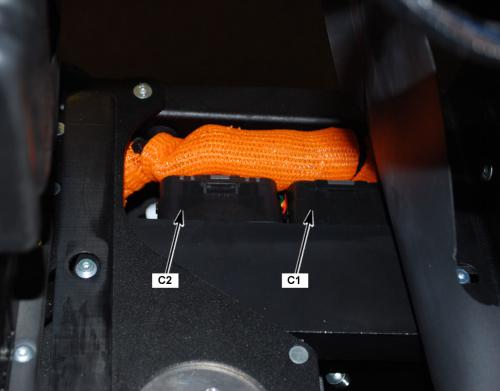
|
C1 Main Bike Board (MBB) |
|||
|
18007
Version 1 21762
Version 2 |
|||
|
Connector Part Information |
|
||
|
Pin |
Wire Color |
Function |
|
| 1 | ORN/RED | Motor Controller Enable | |
| 1 | ORN/RED | Motor Controller Enable | |
| 2 | — | Not Used | |
| 3 | WHT/GRN | ABS Voltage | |
| 4 | BLU/VIO | 12 Volt Positive | |
| 5-6 | — | Not Used | |
| 7 | ORN/BLK | Power Pack Ground | |
| 8 | — | Not Used | |
| 9 | BRN/WHT | System ON Output | |
| 10 | — | Not Used | |
| 11 | YEL/BLK | Kickstand Switch Signal | |
| 12 | ORN/BLK | Kickstand Switch Ground | |
| 13 | WHT/BLU | Check Engine Light Control | |
| 14 | RED | Fuel Gauge 5V Reference | |
| 15 | YEL/GRN | Key ON 12V | |
| 16 | YEL | Temperature Warning Lamp Control | |
| 17 | YEL/BLK | Warning Lamp Control | |
| 18 | ORN/BRN | MBB Low Power | |
| 19 | ORN/GRY | Motor Controller Neutral | |
| 20 | ORN/RED | DC/DC Converter Enable | |
| 21 | — | Not Used | |
| 22 | BLK/WHT | Battery Throttle Enable | |
| 23 | RED | Motor Stop Switch 5V | |
| 24 | RED/BLK | Motor Stop Switch IN | |
| 25-26 | — | Not Used | |
| 27 | RED | Kickstand Switch Signal | |
| 28 | WHT/RED | Brake Switch Input | |
| 29 | BLK | 12 Volt Ground | |
| 30 | BLU/WHT | ABS Indicator Light Control | |
| 31 | ORN | Red Charge Indicator Light Control | |
| 32 | ORN/BLK | Instrument Cluster Light Ground | |
| 33 | VIO | Charge Indicator Control | |
| 34 | RED/WHT | Armed Indicator Light Control | |

| Under the Cover, Below the Front of the Power Pack |
|
COM1458
Loading image...
|
Version 1
|
C2 Main Bike Board (MBB) |
||
|
CON0765
|
||
|
Connector Part Information |
|
|
|
Pin |
Wire Color |
Function |
| 1 | ORN/BLK | Motor Controller Ground |
| 2 | YEL/RED | Motor Controller 24 Volt |
| 3 | BLK | CAN 0 Ground |
| 4 | RED | CAN 0 5 Volts |
| 5 | BLK | CAN 1 Ground |
| 6 | WHT | CAN 2 High |
| 7 | BLU | CAN 2 Low |
| 8 | BLK | CAN 2 Ground |
| 9 | RED | CAN 2 5 Volts |
| 10-12 | — | Not Used |
| 13 | PNK | Loopback Return (HVIL) |
| 14 | PNK | Loopback Source (HVIL) |
| 15 | BLU/BLK | Start Switch Input |
| 16 | — | Not Used |
| 17 | BLK | Ambient Temperature |
| 18 | GRY/RED | On Board Charger Attached |
| 19 | ORN/BLK | On Board Charger Reference |
| 20 | WHT/BLK | On Board Charger Enable |
| 21 | BLU/GRY | CAN Low Motor Controller |
| 22 | WHT/GRY | CAN High Motor Controller |
| 23 | BLU | CAN 0 Low |
| 24 | WHT | CAN 0 High |
| 25 | BLU | CAN 1 Low |
| 26 | WHT | CAN 1 High |
| 27 | BLK/GRY | ABS Off |
| 28 | BLK/GRN | ABS Indicator Input |
| 29 | RED/BLK | U-ART Tx |
| 30 | GRY/BLK | U-ART Rx |
| 31 | ORN/BLK | Diagnostic Ground DLC |
| 31 | BLK | Diagnostic Ground Temperature Sensor |
| 32-33 | — | Not Used |
| 34 | BLU/BRN | Motor Controller Throttle 5V |
| 35 | RED | Ext Switch 5V |
| 36 | GRY/BLU | Chademo Charger Attached (J1772) |
| 37 | BLU/RED | Motor Controller Throttle 5V |
| 38 | WHT/BLK | Ext Charger Enable 0 |
| 39 | — | Not Used |
| 40 | WHT/BRN | Ext Charger Enable 1 |

| Under the Cover, Below the Front of the Power Pack |
|
COM1458
Loading image...
|
Version 1
|
C3 Data Link Connector |
||
|
18502
|
||
|
Connector Part Information |
|
|
|
Pin |
Wire Color |
Function |
| 1-3 | — | Not Used |
| 4 | BLK/BLU | 12 Volt Ground |
| 5 | ORN/BLK | Diagnostic Ground |
| 6 | WHT | CAN 1 High |
| 7 | — | Not Used |
| 8 | RED/BLK | U-Art Tx |
| 9 | GRY/BLK | U-ART Rx |
| 10 | — | Not Used |
| 11 | BLK | CAN 1 Ground |
| 12-13 | — | Not Used |
| 14 | BLU | CAN 1 Low |
| 15-16 | — | Not Used |
| Left Side of the Frame, Between the Horn and the Front Power Pack |
|
COM1907
Loading image...
|

Version 1
|
C7 DC/DC Converter Fuse |
||
|
con0770
|
||
|
Connector Part Information |
|
|
|
Pin |
Wire Color |
Function |
| 1 | ORN | Low Voltage (+) Input |
| 2 | ORN/BLU | Low Voltage (+) Output |
| Below the Power Pack, Across from the MBB, Inside the Harness Cover |
|
COM2000
Loading image...
|
Version 1
|
C8 DC/DC Converter |
||
|
18513
|
||
|
Connector Part Information |
|
|
|
Pin |
Wire Color |
Function |
| 1 | BLK | Accessory 0 Volts |
| 2 | BLU | Accessory 12 Volts |
| 3 | ORN/BLK | Negative Input Voltage |
| 4 | ORN/BLU | Positive Input Voltage |
| 5 | ORN/RED | Converter Control |

| Right Front of the Frame, Under the Front of the Power Pack |
|
COM1473
Loading image...
|

Version 1
|
18512
Loading image...
|
|||||||
| Connector Part Information |
|
Connector Part Information |
|
||||
| Pin | Wire Color | Function | Pin | Wire Color | Function | ||
| 1 | BLU | 5 Volts | 1 | RED | 5 Volts | ||
| 2 | BLK | Battery Negative | 2 | ORN/BLK | Battery Negative | ||
| 3 | PNK | Kickstand Switch IN Signal | 3 | YEL/BLK | Kickstand Switch IN Signal | ||

| Left Side of the Frame, Next to the Brushless Motor Controller |
|
COM2000
Loading image...
|
Version 1
|
19328
Loading image...
|
|||||
| Connector Part Information |
|
Connector Part Information |
|
||
| Pin | Wire Color | Function | Pin | Wire Color | Function |
| A | WHT | Sine Digital Input | A | BLU | Sine Digital Input |
| B | BLU | Cosine Input | B | WHT | Cosine Input |
| C | BLK | Encoder Power Supply (–) | C | BLK | Encoder Power Supply (–) |
| D | — | Not Used | D | — | Not Used |
| E | PNK | Encoder Power Supply (+) | E | RED | Encoder Power Supply (+) |
| F | GRN | Shield | F | — | Shield |
| G | YEL | Motor Controller Ground | G | ORN/BLK | Motor Controller Ground |
| H | YEL | Temperature Sensor Input | H | WHT | Temperature Sensor Input |
| Right Side of the Frame, Next to the Brushless Motor Controller |
|
COM1462
Loading image...
|
Version 1
|
C26 Accessory Power Port |
||
|
CON0759
|
||
|
Connector Part Information |
|
|
|
Pin |
Wire Color |
Function |
| 1 | BLU | Fuse 2 Voltage |
| 2 | BLK | Ground, Accessory 0 V |
| Front Right of the Side Frame, Behind the Right Fairing Panel |
|
com1903
Loading image...
|

Version 1
|
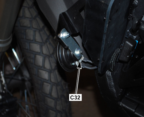
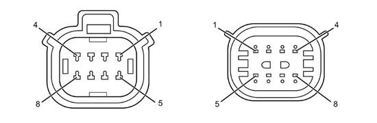
C32 Horn |
||
|
con0758
|
||
|
Connector Part Information |
|
|
|
Pin |
Wire Color |
Function |
|
1 |
BLK/YEL |
Horn Ground Control |

|
C32 Horn |
||
|
con0758
|
||
|
Connector Part Information |
|
|
|
Pin |
Wire Color |
Function |
|
2 |
BLU/BLK |
Horn Supply Voltage |
| Left Front Side of the Frame |
|
com1659
Loading image...
|
Version 1
|
19226
Loading image...
|
|||||
| Connector Part Information |
|
Connector Part Information |
|
||
| Pin | Wire Color | Function | Pin | Wire Color | Function |
| 1 | WHT | Left Front Turn Signal Voltage | 1 | RED/GRN | Left Front Turn Signal Voltage |

|
19226
Loading image...
|
|||||
| Connector Part Information |
|
Connector Part Information |
|
||
| Pin | Wire Color | Function | Pin | Wire Color | Function |
| 2 | BLK | Left Front Turn Signal Ground | 2 | BLK | Left Front Turn Signal Ground |
| Under the Instrument Panel, Behind the Headlight |
|
com1906
Loading image...
|

Version 1
|
19226
Loading image...
|
|||||
| Connector Part Information |
|
Connector Part Information |
|
||
| Pin | Wire Color | Function | Pin | Wire Color | Function |
| 1 | RED | Right Front Turn Signal Voltage | 1 | WHT/GRY | Right Front Turn Signal Voltage |
|
19226
Loading image...
|
|||||
| Connector Part Information |
|
Connector Part Information |
|
||
| Pin | Wire Color | Function | Pin | Wire Color | Function |
| 2 | BLK | Right Front Turn Signal Ground | 2 | BLK | Right Front Turn Signal Ground |
| Under the Instrument Panel, Behind the Headlight |
|
com1906
Loading image...
|
Version 1
|
C35
Loading image...
|
|||||
| Connector Part Information |
|
Connector Part Information |
|
||
| Pin | Wire Color | Function | Pin | Wire Color | Function |
| 1 | — | Not Used | 1 | — | Not Used |
| 2 | BRN | High Beam Input (Flash to Pass) | 2 | RED/GRN | High Beam Input (Flash to Pass) |
| 3 | RED/YEL | Headlamp Low Beam Voltage | 3 | BLK | Headlamp Low Beam Voltage |
| 4 | RED/BLK | Headlamp High Beam Voltage | 4 | WHT | Headlamp High Beam Voltage |
| 5 | BLU/YEL | Headlamp Switch Voltage | 5 | BRN | Headlamp Switch Voltage |
| 6 | BLK/YEL | Horn Voltage | 6 | BLU | Horn Voltage |
| 7 | BLK/WHT | Horn Switch Ground | 7 | GRY | Horn Switch Ground |
| 8 | GRY | Right Turn Signal Lamp Voltage | 8 | RED/BLK | Right Turn Signal Lamp Voltage |
| 9 | GRY/GRN | Turn Signal | 9 | BLK/BLU | Turn Signal |
| 10 | GRN | Left Turn Signal Lamp Voltage | 10 | LT BLU | Left Turn Signal Lamp Voltage |

| Under the Instrument Panel, Behind the Headlight |
|
com1906
Loading image...
|
Version 1
|
CON0661
Loading image...
|
|||||||
| Connector Part Information |
|
Connector Part Information |
|
||||
| Pin | Wire Color | Function | Pin | Wire Color | Function | ||
| 1 | WHT/GRN | Left Rear Turn Signal Voltage | 1 | WHT/GRN | Left Rear Turn Signal Voltage | ||
| 2 | BLK | Left Rear Turn Signal Ground | 2 | BLK | Left Rear Turn Signal Ground | ||
| 3 | RED/GRY | Right Rear Turn Signal Voltage | 3 | RED/GRY | Right Rear Turn Signal Voltage | ||
| 4 | BLK | Right Rear Turn Signal Ground | 4 | BLK | Right Rear Turn Signal Ground | ||
| 5 | WHT/RED | Brake Light | 5 | WHT/RED | Brake Light | ||
| 6 | BLK | Ground | 6 | BLK | Ground | ||
| 7 | BRN | Brake Light Voltage | 7 | BRN | Brake Light Voltage | ||
| 8 | — | Running Light Voltage | 8 | — | Running Light Voltage | ||
| Back of the Frame, Under the Seat |
|
com2005
Loading image...
|
Version 1
|
19227
Loading image...
|
|||||
| Connector Part Information |
|
Connector Part Information |
|
||
| Pin | Wire Color | Function | Pin | Wire Color | Function |
| 1 | BLU/BLK | Foot Brake Switch Supply Voltage | 1 | BLK | Foot Brake Switch Supply Voltage |
| 2 | WHT/RED | Foot Brake Switch Signal | 2 | BLK | Foot Brake Switch Signal |

| On the Right Side of the Frame, Next to the Rear Shock |
|
com2001
Loading image...
|
Version 1
|
19226
Loading image...
|
|||||
| Connector Part Information |
|
Connector Part Information |
|
||
| Pin | Wire Color | Function | Pin | Wire Color | Function |
| 1 | RED | Left Rear Turn Signal Voltage | 1 | WHT/GRN | Left Rear Turn Signal Voltage |
|
19226
Loading image...
|
|||||
| Connector Part Information |
|
Connector Part Information |
|
||
| Pin | Wire Color | Function | Pin | Wire Color | Function |
| 2 | BLK | Left Rear Turn Signal Ground | 2 | BLK | Left Rear Turn Signal Ground |
| Above the Rear Fender |
|
com1464
Loading image...
|

Version 1
|
19226
Loading image...
|
|||||
| Connector Part Information |
|
Connector Part Information |
|
||
| Pin | Wire Color | Function | Pin | Wire Color | Function |
| 1 | WHT | Right Rear Turn Signal Voltage | 1 | RED/GRY | Right Rear Turn Signal Voltage |
|
19226
Loading image...
|
|||||
| Connector Part Information |
|
Connector Part Information |
|
||
| Pin | Wire Color | Function | Pin | Wire Color | Function |
| 2 | BLK | Right Rear Turn Signal Ground | 2 | BLK | Right Rear Turn Signal Ground |
| Above the Rear Fender |
|
com1464
Loading image...
|
Version 1
|
17856
Loading image...
|
|||||
| Connector Part Information |
|
Connector Part Information |
|
||
| Pin | Wire Color | Function | Pin | Wire Color | Function |
| 1 | WHT/RED | Tail Light Ground | 1 | GRN/WHT | Tail Light Ground |
| 2 | BLK | Running Light Supply Ground | 2 | BLK | Running Light Supply Ground |
| 3 | BRN | Brake Light Supply Voltage | 3 | BRN | Brake Light Supply Voltage |

| Above the Rear Fender |
|
com1464
Loading image...
|
Version 1
|
C42 Turn Signal Flasher |
||
|
19225
|
||
|
Connector Part Information |
|
|
|
Pin |
Wire Color |
Function |
| 1 | BLU/BLK | Turn Signal Flasher Voltage |
| 2 | GRY/GRN | Turn Signal Lamp Control |
| 3 | BLK | Ground |

| Front Right Side of the Frame, Behind the Right Fairing Panel |
|
com1902
Loading image...
|

Version 1
|
19226
Loading image...

|
|||||
| Connector Part Information |
|
Connector Part Information |
|
||
| Pin | Wire Color | Function | Pin | Wire Color | Function |
| 1 | WHT | Right Rear Turn Signal Voltage | 1 | RED/GRY | Right Rear Turn Signal Voltage |

|
19226
Loading image...
|
|||||
| Connector Part Information |
|
Connector Part Information |
|
||
| Pin | Wire Color | Function | Pin | Wire Color | Function |
| 2 | BLK | Right Rear Turn Signal Ground | 2 | BLK | Right Rear Turn Signal Ground |
| Above the Rear Fender |
|
com1464
Loading image...
|

Version 1
|
17856
Loading image...
|
|||||
| Connector Part Information |
|
Connector Part Information |
|
||
| Pin | Wire Color | Function | Pin | Wire Color | Function |
| 1 | WHT/RED | Tail Light Ground | 1 | GRN/WHT | Tail Light Ground |
| 2 | BLK | Running Light Supply Ground | 2 | BLK | Running Light Supply Ground |
| 3 | BRN | Brake Light Supply Voltage | 3 | BRN | Brake Light Supply Voltage |

| Above the Rear Fender |
|
com1464
Loading image...
|
Version 1
|
C42 Turn Signal Flasher |
||
|
19225
|
||
|
Connector Part Information |
|
|
|
Pin |
Wire Color |
Function |
| 1 | BLU/BLK | Turn Signal Flasher Voltage |
| 2 | GRY/GRN | Turn Signal Lamp Control |
| 3 | BLK | Ground |

| Front Right Side of the Frame, Behind the Right Fairing Panel |
|
com1902
Loading image...
|

Version 1
|
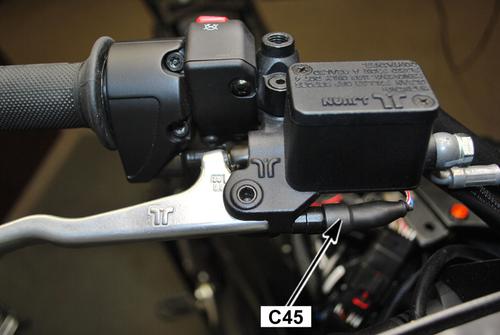
C45 Hand Brake Switch |
|||
|
con0758
Loading image...
|
|||
|
Connector Part Information |
|
||
| Pin | Wire Color | Function | |
| 1 | BLU/BLK |
Hand Brake Switch Supply Voltage |
|

|
C45 Hand Brake Switch |
|||
|
con0758
Loading image...
|
|||
|
Connector Part Information |
|
||
| Pin | Wire Color | Function | |
| 2 | WHT/RED |
Hand Brake Switch Signal |
|
| Right Side of the Handlebar, Under the Master Cylinder |
|
com2008
Loading image...
|
Version 1
|
C46 Fuse Center Connector Bottom View |
||
|
con0873
|
||
|
Connector Part Information |
|
|
|
Pin |
Wire Color |
Function |
|
1 |
BLU |
Fuse 6 Supply Voltage |
|
2 |
BLU |
Fuse 5 Supply Voltage |
|
3 |
BLU |
Fuse 4 Supply Voltage |
|
4 |
BLU |
Fuse 3 Supply Voltage |
|
5 |
BLU |
Fuse 2 Supply Voltage |
|
6 |
BLU |
Fuse 1 Supply Voltage |
|
7 |
BRN |
Voltage to Splice S299 |
|
8 |
BLU/BLK |
Voltage to Splice S27 • Horn • Turn Signal Flasher • Brake Light Switches |
|
9 |
BLU |
Accessory Power Port |
|
9 |
BLU |
Accessory Power Connector |
|
10 |
BLU/YEL |
Voltage to Splice S25 Headlight Switch |
|
11 |
BLU/GRN |
ABS HCU |
|
12 |
BLU/VIO |
ABS HCU |

| Under the Right Side Fairing Panel, Above the Front Power Pack |
|
com1902
Loading image...
|
Version 1
|
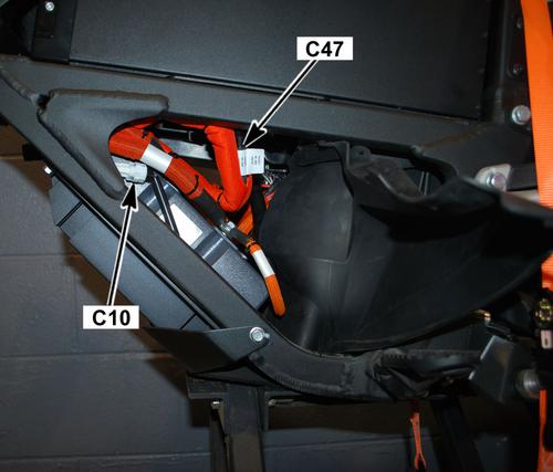
C47 Main Bike Board (MBB) Fuse |
|||
|
con0770
Loading image...
|
|||
|
Connector Part Information |
|
||
| Pin | Wire Color | Function | |
| 1 | ORN |
Low Voltage (+) Input |
|
| 2 | ORN/BRN |
Low Voltage (+) Output |
|

| Below the Front Power Pack, Across From the MBB, Inside the Harness Cover |
|
com1668
Loading image...
|

Version 1
|
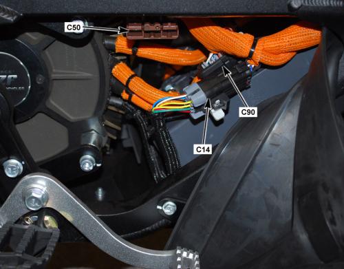
C50 Quick Charge Connector |
||
|
con0761
|
||
|
Connector Part Information |
|
|
|
Pin |
Wire Color |
Function |
|
1 |
BLK |
Fused Battery Positive (+) |
|
1 |
ORN |
Fused Battery Positive (+) |
|
2 |
BLK |
Battery Negative (-) |
|
P1-P2 |
— |
Not Used |
|
S1 |
WHT/BRN |
Charger Enable 1 |
|
S2 |
WHT/BLK |
Charger Enable 0 |

| Right Side of the Frame, Between the Brushless Motor Controller and the Motor |
|
com1462
Loading image...
|

Version 1
|
C57 Charger |
||
|
con0748
|
||
|
Connector Part Information |
|
|
|
Pin |
Wire Color |
Function |
|
1 |
— |
Not Used |
|
2 |
GRY/BLU |
Chademo Charger Attached (J1772) |
|
3 |
ORN/BLK |
B-Output |
|
4 |
BLK |
CAN Ground |
|
5 |
RED |
CAN 5 Volts |
|
6 |
BLU |
CAN 2 Low |
|
7 |
WHT |
CAN 2 High |
|
8 |
— |
Not Used |
|
9 |
ORN |
B+ Output B+ Output |
|
10 |
ORN |
B+ Output |
|
11 |
GRY/RED |
Charger Attached Signal |
|
12 |
WHT/BLK |
Charger Enable |
|
13 |
ORN/BLK |
Charger Ground |
|
14 |
ORN/BLK |
B- Output |
|
15-18 |
— |
Not Used |

| Front of the Frame, Behind the Left Fairing Panel |
|
com1904
Loading image...
|

Version 1
|
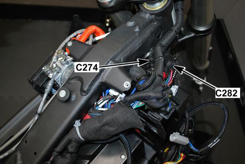
C74 Brushless Motor Controller |
||
|
con0051
Loading image...

|
||
|
Connector Part Information |
|
|
|
Pin |
Wire Color |
Function |
|
— |
BLK (Orange Sleeve Over Cable) |
Positive (+) Voltage |
| Front of the Frame, Below the Front Power Pack |
|
com2006
Loading image...
|

Version 1
|
C76 Brushless Motor Controller |
||
|
con0051
Loading image...
|
||
|
Connector Part Information |
|
|
|
Pin |
Wire Color |
Function |
|
— |
BLK (Orange Sleeve Over Cable) |
Negative (-) Ground |
|
— |
ORN/BLK |
Negative (-) Ground |
| Front of the Frame, Below the Front Power Pack |
|
com2006
Loading image...
|
Version 1
|
C90 Brushless Motor Controller |
||
|
19332
|
||
|
Connector Part Information |
|
|
|
Pin |
Wire Color |
Function |
| 1 | ORN/RED | Voltage From Key Switch |
| 2 | BLU | CAN Termination |
| 3-5 | — | Not Used |
| 6 | ORN/RED | Voltage From Key Switch |
| 7-14 | — | Not Used |
| 15 | BLK | Encoder Power Supply (–) |
| 16 | WHT/GRY | CAN High |
| 17 | — | Not Used |
| 18 | ORN/GRY | Digital Input 1 |
| 19-20 | — | Not Used |
| 21 | BLU | Digital Input 8 |
| 22 | BRN | Throttle Sensor 1 Signal |
| 23 | BRN/RED | Throttle Sensor 1 Signal |
| 24 | BLU | CAN Low |
| 25 | — | Not Used |
| 26 | RED | Encoder Power Supply (+) |
| 27 | BLU/GRY | CAN Low |
| 28 | YEL/RED | CAN Power Supply (+) |
| 29 | — | Not Used |
| 30 | GRY/ORN | Digital Input 2 (Idle Switch) |
| 31-32 | — | Not Used |
| 33 | WHT | Temperature Sensor Input |
| 34 | — | Not Used |
| 35 | WHT | COSINE Input |
| Right Side of the Frame, Next to the Brushless Motor Controller |
|
com1462
Loading image...
|
Version 1
|
C113 Brushless Motor Controller |
||
|
con0051
Loading image...
|
||
|
Connector Part Information |
|
|
|
Pin |
Wire Color |
Function |
| — | BLK (Orange Sleeve Over Cable) | M1 Going to the Motor |
| Front of the Frame, Below the Front Power Pack |
|
com2006
Loading image...
|
Version 1
|
C114 Brushless Motor Connector |
||
|
con0051
Loading image...
|
||
|
Connector Part Information |
|
|
|
Pin |
Wire Color |
Function |
| — | BLK (Orange Sleeve Over Cable) | Going to the Motor |
| Front of the Frame, Below the Front Power Pack |
|
com2006
Loading image...
|
Version 1
|
C115 Brushless Motor Connector |
||
|
con0051
Loading image...
|
||
|
Connector Part Information |
|
|
|
Pin |
Wire Color |
Function |
| — | BLK (Orange Sleeve Over Cable) | Going to the Motor |
| Front of the Frame, Below the Front Power Pack |
|
com2006
Loading image...
|
Version 1
|
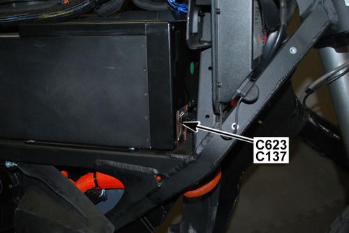
C137 Power Pack (Front) Signal |
||
|
con1010
|
||
|
Connector Part Information |
|
|
|
Pin |
Wire Color |
Function |
| P1 | ORN ORN |
Low Power B+ Low Power B+ |
| P2 | RED | CAN 5 Volts |
| P3 | — | Not Used |
| P4 | YEL/GRY | 12 Volt Output |
| P5 | WHT | CAN High |
| P6 | GRY/BRN | Node ID 0 |
| P7 | GRY/BRN | Node ID 1 |
| P8 | GRY/BRN GRY/BRN |
Ground Ground |
| S1 | BRN | System ON Reference |
| S2 | BLK BRN |
CAN Ground CAN Ground |
| S3 | BRN/WHT | System ON |
| S4 | BLU | CAN Low |
| S5 | PNK | Loopback Output (HVIL) |
| S6 | GRN/YEL | Chassis Ground to C239 |
| S7 | PNK | Loopback Return (HVIL) |
| S8 | BLK/WHT | Throttle Enable |
| Right Front Corner of the Frame |
|
com2007
Loading image...
|
Version 1
|
C207 Charger Fuse |
||
|
con0770
|
||
|
Connector Part Information |
|
|
|
Pin |
Wire Color |
Function |
| 1 | ORN | Low Voltage (+) Input |
| 2 | ORN | Low Voltage (+) Output |
| Right Front of Frame, Under Front Power Pack, Inside the Harness |
|
com1475
Loading image...
|

Version 1
|
C238 Equipment Ground (Fork) |
||
|
con0050
|
||
|
Connector Part Information |
|
|
|
Pin |
Wire Color |
Function |
| — | BLK | Ground |

| Under the Instrument Panel, Behind the Headlight |
|
com1906
Loading image...
|

Version 1
|
C239 Equipment Ground (Frame) |
||
|
con0050
|
||
|
Connector Part Information |
|
|
|
Pin |
Wire Color |
Function |
| — | BLK | Ground |
| — | GRN/YEL | Ground |
| Right Side of the Frame, Behind the Fuse Center (Harness Moved for Clarity) |
|
com1908
Loading image...
|
Version 1
|
18510
Loading image...
|
|||||||
| Connector Part Information |
|
Connector Part Information |
|
||||
| Pin | Wire Color | Function | Pin | Wire Color | Function | ||
| 1 | — | Not Used | 1 | LT BLU | Not Used | ||
| 2 | — | Not Used | 2 | BRN | Not Used | ||
| 3 | YEL/GRY | Key Switch Ground | 3 | RED | Key Switch Ground | ||
| 4 | YEL/GRN | Key Switch Signal | 4 | RED/BLK | Key Switch Signal | ||
| Front Right Side of the Frame, Behind the Right Fairing Panel |
|
com2009
Loading image...
|
Version 1
|
con0753
Loading image...
|
|||||||
| Connector Part Information |
|
Connector Part Information |
|
||||
| Pin | Wire Color | Function | Pin | Wire Color | Function | ||
| 1 | BLU/BLK | Start Switch Signal | 1 | BLK | Start Switch Signal | ||
| 2 | RED | Switch 5 Volts | 2 | BLU/WHT | Switch 5 Volts | ||
| 3 | RED | Motor Stop Switch Output 5 Volts | 3 | RED/WHT | Motor Stop Switch Output 5 Volts | ||
| 4 | RED/BLK | Motor Stop Switch Input | 4 | RED/WHT | Motor Stop Switch Input | ||
| Under the Instrument Panel, Behind the Fly-Screen |
|
com1906
Loading image...
|
Version 1
|
CON0752
Loading image...
|
|||||||
| Connector Part Information |
|
Connector Part Information |
|
||||
| Pin | Wire Color | Function | Pin | Wire Color | Function | ||
| 1 | YEL/BLK | Warning Light Control (red) | 1 | YEL/BLK | Warning Light Control (red) | ||
| 2 | YEL | Temperature Light Control (amber) | 2 | YEL | Temperature Light Control (amber) | ||
| 3 | RED/WHT | Armed Light Control (green) | 3 | GRN/BLK | Armed Light Control (green) | ||
| 4 | VIO | Charge LED Light Control (green) | 4 | WHT/BLK | Charge LED Light Control (green) | ||
| 5 | WHT/BLU | Check Engine Light Control | 5 | BLU | Check Engine Light Control | ||
| 6 | RED/BLK | High Beam Indicator Control (blue) | 6 | BRN/BLK | High Beam Indicator Control (blue) | ||
| 7 | GRN | Left Turn Indicator Control (green) | 7 | GRN | Left Turn Indicator Control (green) | ||
| 8 | GRY | Right Turn Indicator Control (green) | 8 | GRY | Right Turn Indicator Control (green) | ||
| 9 | BLK | Ground 12 Volt | 9 | BLK | Ground 12 Volt | ||
| 10 | RED | State of Charge Control (5 Volt) | 10 | PNK | State of Charge Control (5 Volt) | ||
| 11 | WHT | CAN 2 High | 11 | WHT | CAN 2 High | ||
| 12 | BLU | CAN 2 Low | 12 | BLU | CAN 2 Low | ||
| 13 | ORN/BLK | CAN 2 5 Volts | 13 | ORN/BLK | CAN 2 5 Volts | ||
| 14 | BLU/WHT | ABS | 14 | GRY/BLK | ABS | ||
| 15 | ORN | Charge LED Light Control (red) | 15 | ORN | Charge LED Light Control (red) | ||
| 16 | BRN | 12 Volt Feed | 16 | BRN | 12 Volt Feed | ||
| 17-20 | — | Not Used | 17-20 | — | Not Used | ||

| Front Right Side of the Frame, Behind the Fairing Panel |
|
com2009
Loading image...
|
Version 1
|
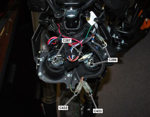
C286 Low Beam Headlight |
|||
|
con0758
Loading image...
|
|||
|
Connector Part Information |
|
||
| Pin | Wire Color | Function | |
| 1 | RED/YEL |
Low Beam Control |
|
|
con0758
Loading image...
|
|||
|
Connector Part Information |
|
||
| Pin | Wire Color | Function | |
| 2 | BLK |
Low Beam Ground |
|
| Behind the Headlight Assembly |
|
com1470
Loading image...
|
Version 1
|
C287 High Beam Headlight |
|||
|
con0758
Loading image...
|
|||
|
Connector Part Information |
|
||
| Pin | Wire Color | Function | |
| 1 | RED/BLK |
High Beam Control |
|
|
con0758
Loading image...
|
|||
|
Connector Part Information |
|
||
| Pin | Wire Color | Function | |
| 2 | BLK |
High Beam Ground |
|
| Behind the Headlight Assembly |
|
com1470
Loading image...
|
Version 1
|
C318 12 Volt Accessory |
||
|
con0749
|
||
|
Connector Part Information |
|
|
|
Pin |
Wire Color |
Function |
| 1 | BLK | Ground, Accessory 0 V |
| 2 | BLU | Fuse 2 Voltage |
| Front Right Side of the Frame, Behind the Right Fairing Panel |
|
com1903
Loading image...
|

Version 1
|
C428 ABS HCU |
||
|
con0869
|
||
|
Connector Part Information |
|
|
|
Pin |
Wire Color |
Function |
| 1 | BLK | Ground |
| 2 | WHT | CAN |
| 3 | BLK/WHT | Front Wheel Speed Sensor (WSS) |
| 4 | WHT/GRN | Wake up voltage from MBB |
| 5-8 | — | Not Used |
| 9 | BLU/GRN | Fuse 2 Voltage |
| 10 | BLK | Motor Ground |
| 11 | BLU | CAN |
| 12 | BLK/RED | Front Wheel Speed Sensor (WSP) |
| 13 | BLK/RED | Rear Wheel Speed Sensor (WSP) |
| 14 | BLK/WHT | Rear Wheel Speed Sensor (WSS) |
| 15 | BLK/GRY | OFF Output |
| 16 | — | Not Used |
| 17 | BLK/GRN | Indicator Control Output |
| 18 | BLU/ORG | In-Line Fuse (ABS Pump) |

| Left Front of the Frame, Above the Front Battery Pack |
|
com1904
Loading image...
|
Version 1
|
C429 Front Wheel Speed Sensor |
||
|
con0462
|
||
|
Connector Part Information |
|
|
|
Pin |
Wire Color |
Function |
| 1 | BLK/RED | WSP |
| 2 | BLK/WHT | WSS |
| Above the Headlight, Behind the Fly-Screen |
|
com1906
Loading image...
|
Version 1
|
C430 Rear Wheel Speed Sensor |
||
|
con0462
|
||
|
Connector Part Information |
|
|
|
Pin |
Wire Color |
Function |
| 1 | BLK/RED | WSP |
| 2 | BLK/WHT | WSS |
| Under the Seat, Above the Front Power Pack |
|
com1904
Loading image...
|
Version 1
|
con0756
Loading image...
|
|||||||
| Connector Part Information |
|
Connector Part Information |
|
||||
| Pin | Wire Color | Function | Pin | Wire Color | Function | ||
| 1 | BRN | Running Light Control | 1 | BRN | Running Light Control | ||
|
con0756
Loading image...
|
|||||||
| Connector Part Information |
|
Connector Part Information |
|
||||
| Pin | Wire Color | Function | Pin | Wire Color | Function | ||
| 2 | BLK | Running Light Ground | 2 | GRN | Running Light Ground | ||
| Behind the Headlight Assembly |
|
com1906
Loading image...
|
Version 1
|
C318 12 Volt Accessory |
||
|
con0749
|
||
|
Connector Part Information |
|
|
|
Pin |
Wire Color |
Function |
| 1 | BLK | Ground, Accessory 0 V |
| 2 | BLU | Fuse 2 Voltage |

| Front Right Side of the Frame, Behind the Right Fairing Panel |
|
com1903
Loading image...

|
Version 1
|
C428 ABS HCU |
||
|
con0869
|
||
|
Connector Part Information |
|
|
|
Pin |
Wire Color |
Function |
| 1 | BLK | Ground |
| 2 | WHT | CAN |
| 3 | BLK/WHT | Front Wheel Speed Sensor (WSS) |
| 4 | WHT/GRN | Wake up voltage from MBB |
| 5-8 | — | Not Used |
| 9 | BLU/GRN | Fuse 2 Voltage |
| 10 | BLK | Motor Ground |
| 11 | BLU | CAN |
| 12 | BLK/RED | Front Wheel Speed Sensor (WSP) |
| 13 | BLK/RED | Rear Wheel Speed Sensor (WSP) |
| 14 | BLK/WHT | Rear Wheel Speed Sensor (WSS) |
| 15 | BLK/GRY | OFF Output |
| 16 | — | Not Used |
| 17 | BLK/GRN | Indicator Control Output |
| 18 | BLU/ORG | In-Line Fuse (ABS Pump) |

| Left Front of the Frame, Above the Front Battery Pack |
|
com1904
Loading image...
|

Version 1
|
C429 Front Wheel Speed Sensor |
||
|
con0462
|
||
|
Connector Part Information |
|
|
|
Pin |
Wire Color |
Function |
| 1 | BLK/RED | WSP |
| 2 | BLK/WHT | WSS |

| Above the Headlight, Behind the Fly-Screen |
|
com1906
Loading image...
|
Version 1
|
C430 Rear Wheel Speed Sensor |
||
|
con0462
|
||
|
Connector Part Information |
|
|
|
Pin |
Wire Color |
Function |
| 1 | BLK/RED | WSP |
| 2 | BLK/WHT | WSS |
| Under the Seat, Above the Front Power Pack |
|
com1904
Loading image...
|
Version 1
|
con0756
Loading image...
|
|||||||
| Connector Part Information |
|
Connector Part Information |
|
||||
| Pin | Wire Color | Function | Pin | Wire Color | Function | ||
| 1 | BRN | Running Light Control | 1 | BRN | Running Light Control | ||

|
con0756
Loading image...
|
|||||||
| Connector Part Information |
|
Connector Part Information |
|
||||
| Pin | Wire Color | Function | Pin | Wire Color | Function | ||
| 2 | BLK | Running Light Ground | 2 | GRN | Running Light Ground | ||
| Behind the Headlight Assembly |
|
com1906
Loading image...
|
Version 1
|
C432A Front Running Light |
||
|
18077
|
||
|
Connector Part Information |
|
|
|
Pin |
Wire Color |
Function |
| 1 | GRN | Running Lamp Ground |
| 2 | BRN | Running Lamp Supply Voltage |
| Bottom of the Headlight |
|
com1485
Loading image...
|
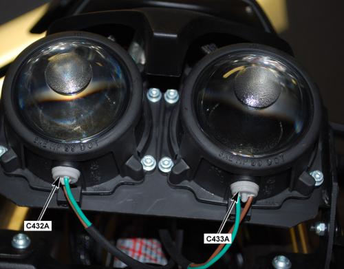
Version 1
|
con0756
Loading image...
|
|||||||
| Connector Part Information |
|
Connector Part Information |
|
||||
| Pin | Wire Color | Function | Pin | Wire Color | Function | ||
| 1 | BRN | Running Light Control | 1 | BRN | Running Light Control | ||
|
con0756
Loading image...
|
|||||||
| Connector Part Information |
|
Connector Part Information |
|
||||
| Pin | Wire Color | Function | Pin | Wire Color | Function | ||
| 2 | BLK | Running Light Ground | 2 | GRN | Running Light Ground | ||
| Behind the Headlight Assembly |
|
com1906
Loading image...
|
Version 1
|
C433A Front Running Light |
||
|
18077
|
||
|
Connector Part Information |
|
|
|
Pin |
Wire Color |
Function |
| 1 | GRN | Running Lamp Ground |
| 2 | BRN | Running Lamp Supply Voltage |
| Bottom of the Headlight |
|
com1485
Loading image...
|
Version 1
|
CON0908
Loading image...
|
|||||||
| Connector Part Information |
|
Connector Part Information |
|
||||
| Pin | Wire Color | Function | Pin | Wire Color | Function | ||
| 1 | BLU/RED | Sensor 2 Voltage 5V | 1 | BLK | Sensor 2 Voltage 5V | ||
| 2 | BRN/RED | Sensor 2 Signal | 2 | BLU | Sensor 2 Signal | ||
| 3 | ORN/BLK | Ground | 3 | WHT | Ground | ||
| 4 | — | Not Used | 4 | BRN | Not Used | ||
| 5 | ORN/BLK | Ground | 5 | ORN | Ground | ||
| 6 | BRN | Sensor 1 Signal | 6 | RED | Sensor 1 Signal | ||
| 7 | BLU/BRN | Sensor 1 Voltage 5V | 7 | YEL | Sensor 1 Voltage 5V | ||
| 8 | GRY/ORN | Idle Switch | 8 | GRN | Idle Switch | ||

| Above the Headlight, Behind the Fly-Screen |
|
com1906
Loading image...
|
Version 1
|
C621 Brushless Motor Controller Connector Face View |
|||
|
con0051
Loading image...

|
|||
|
Connector Part Information |
|
||
| Pin | Wire Color | Function | |
| — | BLK (Orange Sleeve Over Cable |
Positive (+) Power Pack |
|
| Front of the Frame, Below the Front Power Pack |
|
com2006
Loading image...
|

Version 1
|
C622 Brushless Motor Controller Connector View |
||
|
con0051
Loading image...
|
||
|
Connector Part Information |
|
|
|
Pin |
Wire Color |
Function |
| — | BLK (Orange Sleeve Over Cable) | Fused Negative (-) Power Pack |
| Front of the Frame, Below the Front Power Pack |
|
com2006
Loading image...
|
Version 1
|
C623 Power Pack Connector Face View |
||
|
con1011
|
||
|
Connector Part Information |
|
|
|
Pin |
Wire Color |
Function |
| 1 | BLK | Battery Positive (+) |
| 2 | BLK | Battery Positive (-) |

| Right Front Corner of the Frame |
|
com2007
Loading image...
|

Version 1
|
D11 Inline Temperature Sensor |
||
|
Image Not Available
|
||
|
Pin |
Wire Color |
Function |
| 1 | BLK | Temperature Sensor 1 Input |
| 2 | BLK | Ground |
| Left Side of the Frame, Next to the Data Link Connector (DLC) |
|
COM1907
Loading image...
|

Version 1
|
D143 ABS Pump Inline Fuse |
||
|
Image Not Available
|
||
|
Connector Part Information |
|
|
|
Pin |
Wire Color |
Function |
|
1 |
BLU |
Voltage from DC/DC Converter |
|
2 |
BLU/ORN |
Voltage to ABS HCU Converter |
| Under the Right Side Fairing Panel, Above the Front Power Pack |
|
com1902
Loading image...
|

Version 1
|
D317 Charger Fuse Connector Face View |
||
|
con0051
Loading image...
|
||
|
Connector Part Information |
|
|
|
Pin |
Wire Color |
Function |
| 1 | BLK (Orange Sleeve Over Cable) | Positive (+) Output |
|
con0051
Loading image...
|
||
|
Connector Part Information |
|
|
|
Pin |
Wire Color |
Function |
| 2 | BLK (Orange Sleeve Over Cable) | Battery Positive (+) Input |
| Above the Brushless Motor Controller, In Front of the Motor (Part of the Cable) |
|
com1668
Loading image...
|
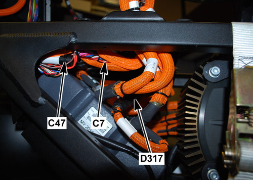
Version 1
Left Side of the Frame, Above the Power Pack

|
Joint |
Connector |
Pin |
Color |
Function |
|
Loading image...
|
C35 | 8 | GRY | Right Turn Signal Input |
|
Loading image...
|
C282 | 8 | GRY | Right Turn Signal Output |
|
Loading image...
|
C36 | 3 | RED/GRY | Right Turn Signal Output |
|
Loading image...
|
C34 | 1 | WHT/GRY | Right Turn Signal Output |
Version 1
Right Side of the Frame, Under the Seat
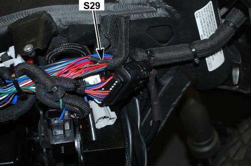
|
Joint |
Connector |
Pin |
Color |
Function |
|
Loading image...
|
C35 | 10 | GRN | Left Turn Signal Input |
|
Loading image...
|
C282 | 7 | GRN | Left Turn Signal Output |
|
Loading image...
|
C36 | 1 | WHT/GRN | Left Turn Signal Output |
|
Loading image...
|
C33 | 1 | RED/GRN | Left Turn Signal Output |
Version 1
Left Side of the Frame, Next to the 12 Volt Fuse Center
|
Joint |
Connector |
Pin |
Color |
Function |
|
Loading image...
|
C8 | 2 | BLU | 12 Volt Input |
|
Loading image...
|
C46 | 1 | BLU | 12 Volt Output |
|
Loading image...
|
C46 | 2 | BLU | 12 Volt Output |
|
Loading image...
|
C46 | 3 | BLU | 12 Volt Output |
| C46 | 4 | BLU | 12 Volt Output | |
| C46 | 5 | BLU | 12 Volt Output | |
| C46 | 6 | BLU | 12 Volt Output | |
| C143 | 1 | BLU | 12 Volt Output |
Version 1
Above the Battery Charger
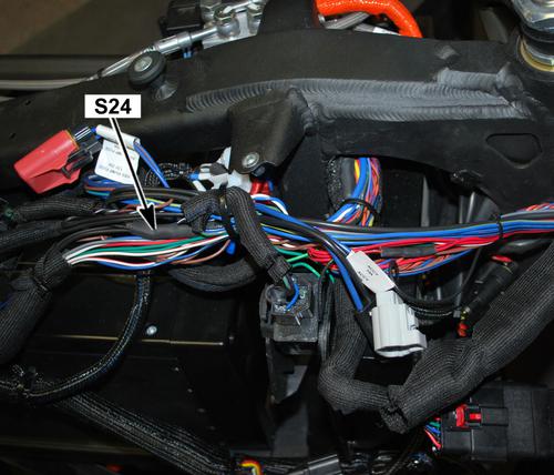
|
Joint |
Connector |
Pin |
Color |
Function |
|
Loading image...
|
C8 | 1 | BLK | 12 Volt Ground Input |
|
Loading image...
|
S257 | — | BLK | 12 Volt Ground Output |
|
Loading image...
|
C1 | 29 | BLK | 12 Volt Ground Output |
|
Loading image...
|
C282 | 9 | BLK | 12 Volt Ground Output |
|
Loading image...
|
C3 | 4 | BLK/BLU | 12 Volt Ground Output |
Version 1
Front of the Motorcycle, Under the Instrument Panel
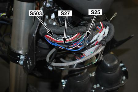
|
Joint |
Connector |
Pin |
Color |
Function |
|
Loading image...
|
C46 | 10 | BLU/YEL | 12 Volt Input (Fuse 3) |
|
Loading image...
|
C35 | 5 | BLU/YEL | High/Low Beam Headlight |
|
Loading image...
|
C35 | 2 | BRN | Flash to Pass |
Version 1
Front of the Motorcycle, Under the Instrument Panel
|
Joint |
Connector |
Pin |
Color |
Function |
|
Loading image...
|
C46 | 8 | BLU/BLK | 12 Volt Input (fuse 5) |
|
Loading image...
|
C38 | 1 | BLU/BLK | Foot Brake Light Switch |
|
Loading image...
|
C45 | 1 | BLU/BLK | Hand Brake Light Switch |
|
Loading image...
|
C42 | 1 | BLU/BLK | Turn Signal Flasher |
|
Loading image...
|
C32 | 2 | BLU/BLK | Horn |
Version 1
Left Side of the Frame, Next to the Fuse Center
|
Joint |
Connector |
Pin |
Color |
Function |
|
Loading image...
|
C35 | 4 | RED/BLK | Headlight Switch Output |
|
Loading image...
|
C287 | 1 | RED/BLK | Headlight Switch Output |
|
Loading image...
|
C282 | 6 | RED/BLK | I/P High Beam Indicator Control Input |
Version 1
Right Side of the Frame, Under the Seat
|
Joint |
Connector |
Pin |
Color |
Function |
|
Loading image...
|
C45 | 2 | WHT/RED | Hand Brake Light Switch Output |
|
Loading image...
|
C36 | 5 | WHT/RED | Brake Light Input |
|
Loading image...
|
C38 | 2 | WHT/RED | Foot Brake Light Switch Output |
|
Loading image...
|
C1 | 28 | WHT/RED | Brake Light Switch Input |
Version 1
Right Side of the Frame, Next to the Brushless Motor Controller Connector

|
Joint |
Connector |
Pin |
Color |
Function |
|
Loading image...
|
C76 | 1 | ORN/BLK | Brushless Motor Controller (ground) |
|
Loading image...
|
C2 | 1 | ORN/BLK | Main Bike Board (MBB) |
|
Loading image...
|
C1 | 7 | ORN/BLK | Main Bike Board (MBB) |
|
Loading image...
|
C14 | G | ORN/BLK | Motor |
|
Loading image...
|
C459 | 3 | ORN/BLK | Throttle |
|
Loading image...
|
C459 | 5 | ORN/BLK | Throttle |
|
Loading image...
|
C8 | 3 | ORN/BLK | DC/DC Converter |
|
Loading image...
|
C57 | 3 | ORN/BLK | Charger |
|
Loading image...
|
C57 | 14 | ORN/BLK | Charger |
Version 1
Left Side of the Frame, Next to the Fuse Center
|
Joint |
Connector |
Pin |
Color |
Function |
|
Loading image...
|
S24 | - | BLK | 12 Volt Ground Input |
|
Loading image...
|
C36 | 4 | BLK | 12 Volt Ground Output to Right Rear Turn Signal |
|
Loading image...
|
C36 | 6 | BLK | 12 Volt Ground Output |
|
Loading image...
|
C428 | 1 | BLK | 12 Volt Ground Output |
|
Loading image...
|
C428 | 10 | BLK | 12 Volt Ground Output |
|
Loading image...
|
C36 | 2 | BLK | 12 Volt Ground Output to Left Rear Turn Signal |
|
Loading image...
|
C42 | 3 | BLK | 12 Volt Ground Output to Turn Signal Flasher |
|
Loading image...
|
C26 | 2 | BLK | 12 Volt Ground Output |
|
Loading image...
|
C318 | 1 | BLK | 12 Volt Ground Output |
|
Loading image...
|
S503 | - | BLK | 12 Volt Ground Output |
Version 1
Left Side of the Frame, Above the Front of the Power Pack
|
Joint |
Connector |
Pin |
Color |
Function |
|
Loading image...
|
C46 | 7 | BRN | Fuse 4 Output |
|
Loading image...
|
C36 | 7 | BRN | Tail Light 12 Volts |
|
Loading image...
|
C432 | 1 | BRN | Front Running Light 1 12 Volts |
|
Loading image...
|
C282 | 16 | BRN | Instrument Panel 12 Volts |
|
Loading image...
|
C433 | 1 | BRN | Front Running Light 2 12 Volts |
Version 1
Below the Front Power Pack, Across from the Main Bike Board
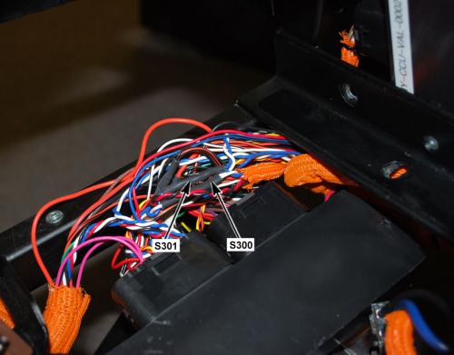
|
Joint |
Connector |
Pin |
Color |
Function |
|
Loading image...
|
C2 | 6 | WHT | Main Bike Board CAN 2 High Output |
|
Loading image...
|
C57 | 7 | WHT | Charger |
|
Loading image...
|
C282 | 11 | WHT | Instrument Panel |
Version 1
Below the Front Power Pack, Across from the Main Bike Board
|
Joint |
Connector |
Pin |
Color |
Function |
|
Loading image...
|
C2 | 7 | BLU | Main Bike Board CAN 2 Low Output |
|
Loading image...
|
C57 | 6 | BLU | Charger |
|
Loading image...
|
C282 | 12 | BLU | Instrument Panel |
Version 1
Left Side of the Frame, Next to the Fuse Center

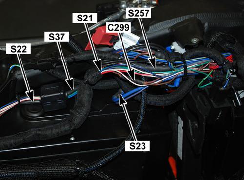
|
Joint |
Connector |
Pin |
Color |
Function |
|
Loading image...
|
S24 | - | BLK | 12 Volt Ground Input |
|
Loading image...
|
C36 | 4 | BLK | 12 Volt Ground Output to Right Rear Turn Signal |
|
Loading image...
|
C36 | 6 | BLK | 12 Volt Ground Output |
|
Loading image...
|
C428 | 1 | BLK | 12 Volt Ground Output |
|
Loading image...
|
C428 | 10 | BLK | 12 Volt Ground Output |
|
Loading image...
|
C36 | 2 | BLK | 12 Volt Ground Output to Left Rear Turn Signal |
|
Loading image...
|
C42 | 3 | BLK | 12 Volt Ground Output to Turn Signal Flasher |
|
Loading image...
|
C26 | 2 | BLK | 12 Volt Ground Output |
|
Loading image...
|
C318 | 1 | BLK | 12 Volt Ground Output |
|
Loading image...
|
S503 | - | BLK | 12 Volt Ground Output |
Version 1
Left Side of the Frame, Above the Front of the Power Pack
|
Joint |
Connector |
Pin |
Color |
Function |
|
Loading image...
|
C46 | 7 | BRN | Fuse 4 Output |
|
Loading image...
|
C36 | 7 | BRN | Tail Light 12 Volts |
|
Loading image...
|
C432 | 1 | BRN | Front Running Light 1 12 Volts |
|
Loading image...
|
C282 | 16 | BRN | Instrument Panel 12 Volts |
|
Loading image...
|
C433 | 1 | BRN | Front Running Light 2 12 Volts |
Version 1
Below the Front Power Pack, Across from the Main Bike Board

|
Joint |
Connector |
Pin |
Color |
Function |
|
Loading image...
|
C2 | 6 | WHT | Main Bike Board CAN 2 High Output |
|
Loading image...
|
C57 | 7 | WHT | Charger |
|
Loading image...
|
C282 | 11 | WHT | Instrument Panel |
Version 1
Below the Front Power Pack, Across from the Main Bike Board
|
Joint |
Connector |
Pin |
Color |
Function |
|
Loading image...
|
C2 | 7 | BLU | Main Bike Board CAN 2 Low Output |
|
Loading image...
|
C57 | 6 | BLU | Charger |
|
Loading image...
|
C282 | 12 | BLU | Instrument Panel |
Version 1
Behind the Headlight

|
Joint |
Connector |
Pin |
Color |
Function |
|
Loading image...
|
S257 | - | BLK | 12 Volt Ground Input |
|
Loading image...
|
C433 | 2 | BLK | 12 Volt Ground Output |
|
Loading image...
|
C432 | 2 | BLK | 12 Volt Ground Output |
|
Loading image...
|
C286 | 2 | BLK | 12 Volt Ground Output |
|
Loading image...
|
C287 | 2 | BLK | 12 Volt Ground Output |
|
Loading image...
|
C35 | 7 | BLK/WHT | 12 Volt Ground Output |
|
Loading image...
|
C33 | 2 | BLK | 12 Volt Ground Output |
|
Loading image...
|
C34 | 2 | BLK | 12 Volt Ground Output |
Version 1
|
SCH3515
Loading image...
|
Version 1

|
SCH2762
Loading image...
|
Version 1
|
SCH2763
Loading image...
|
Version 1

|
SCH3516
Loading image...
|
Version 1
|
SCH3522
Loading image...
|
Version 1
|
SCH3459A
Loading image...
|

Version 1
|
SCH3492
Loading image...
|
Version 1
|
SCH2769A
Loading image...
|

Version 1
|
SCH3519
Loading image...
|
Version 1


|
SCH3525
Loading image...
|

Version 1
|
SCH2776
Loading image...
|

Version 1
|
SCH3482
Loading image...
|

Version 1
|
SCH2769A
Loading image...

|

Version 1
|
SCH3519
Loading image...
|

Version 1
|
SCH3525
Loading image...
|
Version 1
|
SCH2776
Loading image...
|
Version 1
|
SCH3482
Loading image...
|
Version 1
|
SCH2770
Loading image...
|
Version 1
|
SCH2724A
Loading image...
|

Version 1

|
SCH3523
Loading image...
|
Version 1
|
SCH3521
Loading image...
|
Version 1

|
SCH3503A
Loading image...
|

Version 1

|
SCH2781A
Loading image...
|

Version 1

|
SCH2760A
Loading image...
|

Version 1
|
SCH2778
Loading image...
|

Version 1
|
SCH3526A
Loading image...
|

Version 1
|
SCH2760A
Loading image...

|
Version 1
|
SCH2778
Loading image...
|
Version 1
|
SCH3526A
Loading image...
|

Version 1
|
SCH3517
Loading image...
|
Version 1
|
C1 Main Bike Board (MBB) |
|||
|
18007
|
|||
|
Connector Part Information |
|
||
|
Pin |
Wire Color |
Function |
|
| 1 | ORN/RED ORN/RED |
Motor Controller Enable Motor Controller Enable |
|
| 2 | — | Not Used | |
| 3 | BLU/VIO | Motor Controller Digital Input 3 | |
| 4 | BLU | 12 Volt Positive | |
| 5-6 | — | Not Used | |
| 7 | ORN/BLK | Power Pack Ground | |
| 8 | BRN | System ON Signal | |
| 9 | BRN/WHT | System ON Output | |
| 10 | — | Not Used | |
| 11 | YEL/BLK | Kickstand Switch Signal | |
| 12 | ORN/BLK | Kickstand Switch Ground | |
| 13 | WHT/BLU | Check Engine Light Control | |
| 14 | RED | Fuel Gauge 5V Reference | |
| 15 | YEL/GRN | Key ON 12V | |
| 16 | YEL | Temperature Warning Lamp Control | |
| 17 | YEL/BLK | Warning Lamp Control | |
| 18 | ORN/BRN | MBB Low Power | |
| 19 | ORN/GRY | Motor Controller Neutral | |
| 20 | ORN/RED | DC/DC Converter Enable | |
| 21 | — | Not Used | |
| 22 | BLK/WHT | Battery Throttle Enable | |
| 23 | RED | Motor Stop Switch 5V | |
| 24 | RED/BLK | Motor Stop Switch IN | |
| 25-26 | — | Not Used | |
| 27 | RED | Kickstand Switch Signal | |
| 28 | WHT/RED | Brake Switch Input | |
| 29 | BLK | 12 Volt Ground | |
| 30 | BLU/WHT | ABS Indicator Light Control | |
| 31 | ORN | Red Charge Indicator Light Control | |
| 32 | ORN/BLK | Instrument Cluster Light Ground | |
| 33 | VIO | Charge Indicator Control | |
| 34 | RED/WHT | Armed Indicator Light Control | |
| Under the Cover, Below the Front Power Pack |
|
COM1458
Loading image...
|

Version 1
|
C2 Main Bike Board (MBB) |
||
|
CON0765
|
||
|
Connector Part Information |
|
|
|
Pin |
Wire Color |
Function |
| 1 | ORN/BLK | Motor Controller Ground |
| 2 | YEL/RED | Motor Controller 24 Volt |
| 3 | BLK | CAN 0 Ground |
| 4 | RED | CAN 0 5 Volts |
| 5 | BLK | CAN 1 Ground |
| 6 | WHT WHT |
CAN 2 High CAN 2 High |
| 7 | BLU BLU |
CAN 2 Low CAN 2 Low |
| 8 | BLK | CAN 2 Ground |
| 9 | RED | CAN 2 5 Volts |
| 10 | RED/ORN | Diagnostic 3 3 Volts |
| 11-12 | — | Not Used |
| 13 | PNK | Loopback Return (HVIL) |
| 14 | PNK | Loopback Source (HVIL) |
| 15 | BLU/BLK | Start Switch Input |
| 16 | — | Not Used |
| 17 | BLK | Ambient Temperature |
| 18 | GRY/RED | On Board Charger Attached |
| 19 | ORN/BLK | On Board Charger Reference |
| 20 | WHT/BLK | On Board Charger Enable |
| 21 | BLU/GRY | CAN Low Motor Controller |
| 22 | WHT/GRY | CAN High Motor Controller |
| 23 | BLU | CAN 0 Low |
| 24 | WHT | CAN 0 High |
| 25 | BLU | CAN 1 Low |
| 26 | WHT/BLU | CAN 1 High |
| 27 | BLK/GRY | ABS Off |
| 28 | BLK/GRN | ABS Indicator Input |
| 29 | RED/BLK | U-ART Tx |
| 30 | GRY/BLK | U-ART Rx |
| 31 | ORN/BLK BLK |
Diagnostic Ground Diagnostic Ground |
| 32-33 | — | Not Used |
| 34 | BLU/BRN | Motor Controller Throttle 5V |
| 35 | RED | Ext Switch 5V |
| 36 | GRY/BLU | Chademo Charger Attached (J1772) |
| 37 | BLU/RED | Motor Controller Throttle 5V |
| 38 | WHT/BLK | Ext Charger Enable 0 |
| 39 | — | Not Used |
| 40 | WHT/BRN | Ext Charger Enable 1 |
| Under the Cover, Below the Front Power Pack |
|
COM1458
Loading image...
|
Version 1
|
C3 Data Link Connector |
||
|
18502
|
||
|
Connector Part Information |
|
|
|
Pin |
Wire Color |
Function |
| 1-3 | — | Not Used |
| 4 | BLK/BLU | 12 Volt Ground |
| 5 | ORN/BLK | Diagnostic Ground |
| 6 | WHT | CAN 1 High |
| 7 | — | Not Used |
| 8 | RED/BLK | U-Art Tx |
| 9 | GRY/BLK | U-ART Rx |
| 10 | — | Not Used |
| 11 | BLK | CAN 1 Ground |
| 12 | RED/ORN | Diagnostic 3.3 Volts |
| 13 | — | Not Used |
| 14 | BLU | CAN 1 Low |
| 15-16 | — | Not Used |

| Left Side of the Frame, Between the Horn and the Front Power Pack |
|
COM1907
Loading image...
|

Version 1
|
C7 DC/DC Converter Fuse |
||
|
con0770
|
||
|
Connector Part Information |
|
|
|
Pin |
Wire Color |
Function |
| 1 | ORN | Low Voltage (+) Input |
| 2 | ORN/BLU | Low Voltage (+) Output |

| Below the Front Power Pack, Across from the MBB, Inside the Harness Cover |
|
COM1668
Loading image...
|

Version 1
|
C8 DC/DC Converter |
||
|
18513
|
||
|
Connector Part Information |
|
|
|
Pin |
Wire Color |
Function |
| 1 | BLK | Accessory 0 Volts |
| 2 | BLU | Accessory 12 Volts |
| 3 | ORN/BLK | Negative Input Voltage |
| 4 | ORN/BLU | Positive Input Voltage |
| 5 | ORN/RED | Converter Control |
| Right Front of the Frame, Under the Front Power Pack |
|
COM1473
Loading image...
|
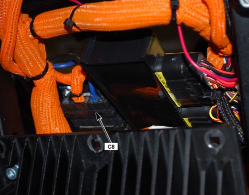
Version 1
|
18512
Loading image...
|
|||||||
| Connector Part Information |
|
Connector Part Information |
|
||||
| Pin | Wire Color | Function | Pin | Wire Color | Function | ||
| 1 | BLU | 5 Volts | 1 | RED | 5 Volts | ||
| 2 | BLK | Battery Negative | 2 | ORN/BLK | Battery Negative | ||
| 3 | PNK | Kickstand Switch IN Signal | 3 | YEL/BLK | Kickstand Switch IN Signal | ||
| Left Side of the Frame, Next to the Brushless Motor Controller |
|
COM1663
Loading image...
|
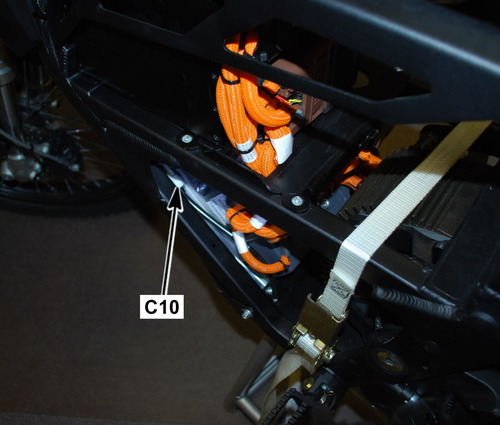
Version 1
|
19328
Loading image...
|
|||||
| Connector Part Information |
|
Connector Part Information |
|
||
| Pin | Wire Color | Function | Pin | Wire Color | Function |
| A | WHT | Sine Digital Input | A | BLU | Sine Digital Input |
| B | BLU | Cosine Input | B | WHT | Cosine Input |
| C | BLK | Encoder Power Supply (–) | C | BLK | Encoder Power Supply (–) |
| D | — | Not Used | D | — | Not Used |
| E | RED | Encoder Power Supply (+) | E | RED | Encoder Power Supply (+) |
| F | GRN | Shield | F | — | Shield |
| G | YEL | Motor Controller Ground | G | ORN/BLK | Motor Controller Ground |
| H | YEL | Temperature Sensor Input | H | WHT | Temperature Sensor Input |

| Right Side of the Frame, Next to the Brushless Motor Controller |
|
COM1462
Loading image...
|

Version 1
|
C26 Accessory Power Port |
||
|
CON0759
|
||
|
Connector Part Information |
|
|
|
Pin |
Wire Color |
Function |
| 1 | BLU | Fuse 2 Voltage |
| 2 | BLK | Ground, Accessory 0 V |

| Front Right of the Side Frame, Behind the Right Fairing Panel |
|
com1903
Loading image...
|

Version 1
|
C32 Horn |
||
|
con0758
|
||
|
Connector Part Information |
|
|
|
Pin |
Wire Color |
Function |
|
1 |
BLK/YEL |
Horn Ground Control |
|
C32 Horn |
||
|
con0758
|
||
|
Connector Part Information |
|
|
|
Pin |
Wire Color |
Function |
|
2 |
BLU/BLK |
Horn Supply Voltage |
| Left Front Side of the Frame |
|
com1659
Loading image...
|

Version 1
|
19226
Loading image...
|
|||||
| Connector Part Information |
|
Connector Part Information |
|
||
| Pin | Wire Color | Function | Pin | Wire Color | Function |
| 1 | WHT | Left Front Turn Signal Voltage | 1 | GRN | Left Front Turn Signal Voltage |
|
19226
Loading image...
|
|||||
| Connector Part Information |
|
Connector Part Information |
|
||
| Pin | Wire Color | Function | Pin | Wire Color | Function |
| 2 | BLK | Left Front Turn Signal Ground | 2 | BLK | Left Front Turn Signal Ground |
| Under the Instrument Panel, Behind the Headlight |
|
com1906
Loading image...
|

Version 1
|
19226
Loading image...
|
|||||
| Connector Part Information |
|
Connector Part Information |
|
||
| Pin | Wire Color | Function | Pin | Wire Color | Function |
| 1 | RED | Right Front Turn Signal Voltage | 1 | GRY | Right Front Turn Signal Voltage |
|
19226
Loading image...
|
|||||
| Connector Part Information |
|
Connector Part Information |
|
||
| Pin | Wire Color | Function | Pin | Wire Color | Function |
| 2 | BLK | Right Front Turn Signal Ground | 2 | BLK | Right Front Turn Signal Ground |
| Under the Instrument Panel, Behind the Headlight |
|
com1906
Loading image...
|
Version 1
|
C35
Loading image...
|
|||||
| Connector Part Information |
|
Connector Part Information |
|
||
| Pin | Wire Color | Function | Pin | Wire Color | Function |
| 1 | — | Not Used | 1 | — | Not Used |
| 2 | BRN | High Beam Input (Flash to Pass) | 2 | RED/GRN | High Beam Input (Flash to Pass) |
| 3 | RED/YEL | Headlamp Low Beam Voltage | 3 | BLK | Headlamp Low Beam Voltage |
| 4 | RED/BLK | Headlamp High Beam Voltage | 4 | WHT | Headlamp High Beam Voltage |
| 5 | BLU/YEL | Headlamp Switch Voltage | 5 | BRN | Headlamp Switch Voltage |
| 6 | BLK/YEL | Horn Voltage | 6 | BLU | Horn Voltage |
| 7 | BLK/WHT | Horn Switch Ground | 7 | GRY | Horn Switch Ground |
| 8 | GRY | Right Turn Signal Lamp Voltage | 8 | RED/BLK | Right Turn Signal Lamp Voltage |
| 9 | GRY/GRN | Turn Signal | 9 | BLK/BLU | Turn Signal |
| 10 | GRN | Left Turn Signal Lamp Voltage | 10 | LT BLU | Left Turn Signal Lamp Voltage |
| Under the Instrument Panel, Behind the Headlight |
|
com1906
Loading image...
|
Version 1
|
CON0661
Loading image...
|
|||||||
| Connector Part Information |
|
Connector Part Information |
|
||||
| Pin | Wire Color | Function | Pin | Wire Color | Function | ||
| 1 | WHT/GRN | Left Rear Turn Signal Voltage | 1 | WHT/GRN | Left Rear Turn Signal Voltage | ||
| 2 | BLK | Left Rear Turn Signal Ground | 2 | BLK | Left Rear Turn Signal Ground | ||
| 3 | RED/GRY | Right Rear Turn Signal Voltage | 3 | RED/GRY | Right Rear Turn Signal Voltage | ||
| 4 | BLK | Right Rear Turn Signal Ground | 4 | BLK | Right Rear Turn Signal Ground | ||
| 5 | WHT/RED | Brake Light | 5 | WHT/RED | Brake Light | ||
| 6 | BLK | Ground | 6 | BLK | Ground | ||
| 7 | BRN | Brake Light Voltage | 7 | BRN | Brake Light Voltage | ||
| 8 | — | Running Light Voltage | 8 | — | Running Light Voltage | ||

| Back of the Frame, Under the Seat |
|
com2005
Loading image...
|

Version 1
|
19227
Loading image...
|
|||||
| Connector Part Information |
|
Connector Part Information |
|
||
| Pin | Wire Color | Function | Pin | Wire Color | Function |
| 1 | BLU/BLK | Foot Brake Switch Supply Voltage | 1 | BLK | Foot Brake Switch Supply Voltage |
| 2 | WHT/RED | Foot Brake Switch Signal | 2 | BLK | Foot Brake Switch Signal |
| On the Right Side of the Frame, Next to the Rear Shock |
|
com1664
Loading image...
|
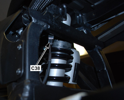
Version 1
|
19226
Loading image...
|
|||||
| Connector Part Information |
|
Connector Part Information |
|
||
| Pin | Wire Color | Function | Pin | Wire Color | Function |
| 1 | RED | Left Rear Turn Signal Voltage | 1 | WHT/GRN | Left Rear Turn Signal Voltage |
|
19226
Loading image...
|
|||||
| Connector Part Information |
|
Connector Part Information |
|
||
| Pin | Wire Color | Function | Pin | Wire Color | Function |
| 2 | BLK | Left Rear Turn Signal Ground | 2 | BLK | Left Rear Turn Signal Ground |
| Above the Rear Fender |
|
com1464
Loading image...
|
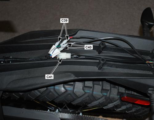
Version 1
|
19226
Loading image...
|
|||||
| Connector Part Information |
|
Connector Part Information |
|
||
| Pin | Wire Color | Function | Pin | Wire Color | Function |
| 1 | WHT | Right Rear Turn Signal Voltage | 1 | RED/GRY | Right Rear Turn Signal Voltage |
|
19226
Loading image...
|
|||||
| Connector Part Information |
|
Connector Part Information |
|
||
| Pin | Wire Color | Function | Pin | Wire Color | Function |
| 2 | BLK | Right Rear Turn Signal Ground | 2 | BLK | Right Rear Turn Signal Ground |
| Above the Rear Fender |
|
com1464
Loading image...
|
Version 1
|
17856
Loading image...
|
|||||
| Connector Part Information |
|
Connector Part Information |
|
||
| Pin | Wire Color | Function | Pin | Wire Color | Function |
| 1 | WHT/RED | Tail Light Ground | 1 | GRN/WHT | Tail Light Ground |
| 2 | BLK | Running Light Supply Ground | 2 | BLK | Running Light Supply Ground |
| 3 | BRN | Brake Light Supply Voltage | 3 | BRN | Brake Light Supply Voltage |
| Above the Rear Fender |
|
com1464
Loading image...
|
Version 1
|
C42 Turn Signal Flasher |
||
|
19225
|
||
|
Connector Part Information |
|
|
|
Pin |
Wire Color |
Function |
| 1 | BLU/BLK | Turn Signal Flasher Voltage |
| 2 | GRY/GRN | Turn Signal Lamp Control |
| 3 | BLK | Ground |
| Front Right Side of the Frame, Behind the Right Fairing Panel |
|
com1902
Loading image...
|

Version 1
|
C45 Hand Brake Switch |
|||
|
con0758
Loading image...
|
|||
|
Connector Part Information |
|
||
| Pin | Wire Color | Function | |
| 1 | BLU/BLK |
Hand Brake Switch Supply Voltage |
|
|
C45 Hand Brake Switch |
|||
|
con0758
Loading image...
|
|||
|
Connector Part Information |
|
||
| Pin | Wire Color | Function | |
| 2 | WHT/RED |
Hand Brake Switch Signal |
|
| Right Side of the Handlebar, Under the Master Cylinder |
|
com1585
Loading image...
|
Version 1
|
C46 Fuse Center Connector Bottom View |
||
|
con0873
|
||
|
Connector Part Information |
|
|
|
Pin |
Wire Color |
Function |
|
1 |
BLU |
Fuse 6 Supply Voltage |
|
2 |
BLU |
Fuse 5 Supply Voltage |
|
3 |
BLU |
Fuse 4 Supply Voltage |
|
4 |
BLU |
Fuse 3 Supply Voltage |
|
5 |
BLU |
Fuse 2 Supply Voltage |
|
6 |
BLU/VIO |
Fuse 1 Supply Voltage |
|
7 |
BRN |
Voltage to Splice S299 |
|
8 |
BLU/BLK |
Voltage to Splice S27 • Horn • Turn Signal Flasher • Brake Light Switches |
|
9 |
BLU |
Accessory Power Port |
|
9 |
BLU |
Accessory Power Connector |
|
10 |
BLU/YEL |
Voltage to Splice S25 Headlight Switch |
|
11 |
BLU/GRN |
ABS HCU |
|
12 |
BLU/ORN |
ABS HCU |
| Under the Right Side Fairing Panel, Above the Front Power Pack |
|
com1902
Loading image...
|
Version 1
|
C47 Main Bike Board (MBB) Fuse |
|||
|
con0770
Loading image...
|
|||
|
Connector Part Information |
|
||
| Pin | Wire Color | Function | |
| 1 | ORN |
Low Voltage (+) Input |
|
| 2 | ORN/BRN |
Low Voltage (+) Output |
|
| Below the Front Power Pack, Across From the MBB, Inside the Harness Cover |
|
com1668
Loading image...
|

Version 1
|
C50 Quick Charge |
||
|
con0761
|
||
|
Connector Part Information |
|
|
|
Pin |
Wire Color |
Function |
|
1 |
BLK |
Fused Battery Positive (+) |
|
1 |
ORN |
Fused Battery Positive (+) |
|
2 |
BLK |
Battery Negative (-) |
|
P1-P2 |
— |
Not Used |
|
S1 |
WHT/BRN |
Charger Enable 1 |
|
S2 |
WHT/BLK |
Charger Enable 0 |
| Right Side of the Frame, Between the Brushless Motor Controller and the Motor |
|
com1462
Loading image...
|

Version 1
|
C57 Charger |
||
|
con0748
|
||
|
Connector Part Information |
|
|
|
Pin |
Wire Color |
Function |
|
1 |
— |
Not Used |
|
2 |
GRY/BLU |
Chademo Charger Attached (J1772) |
|
3 |
ORN/BLK |
B-Output |
|
4 |
BLK |
CAN Ground |
|
5 |
RED |
CAN 5 Volts |
|
6 |
BLU |
CAN 2 Low |
|
7 |
WHT |
CAN 2 High |
|
8 |
— |
Not Used |
|
9 |
ORN |
B+ Output |
|
10 |
— |
Not Used |
|
11 |
GRY/RED |
Charger Attached Signal |
|
12 |
WHT/BLK |
Charger Enable |
|
13 |
ORN/BLK |
Charger Ground |
|
14 |
ORN/BLK |
B- Output |
|
15-18 |
— |
Not Used |

| Front of the Frame, Behind the Left Fairing Panel |
|
com1904
Loading image...
|
Version 1
|
C74 Brushless Motor Controller |
||
|
con0051
Loading image...

|
||
|
Connector Part Information |
|
|
|
Pin |
Wire Color |
Function |
|
— |
BLK (Orange Sleeve Over Cable) |
Positive (+) Voltage |
| Front of the Frame, Below the Front Power Pack |
|
com1467
Loading image...
|

Version 1
|
C50 Quick Charge |
||
|
con0761
|
||
|
Connector Part Information |
|
|
|
Pin |
Wire Color |
Function |
|
1 |
BLK |
Fused Battery Positive (+) |
|
1 |
ORN |
Fused Battery Positive (+) |
|
2 |
BLK |
Battery Negative (-) |
|
P1-P2 |
— |
Not Used |
|
S1 |
WHT/BRN |
Charger Enable 1 |
|
S2 |
WHT/BLK |
Charger Enable 0 |

| Right Side of the Frame, Between the Brushless Motor Controller and the Motor |
|
com1462
Loading image...

|

Version 1
|
C57 Charger |
||
|
con0748
|
||
|
Connector Part Information |
|
|
|
Pin |
Wire Color |
Function |
|
1 |
— |
Not Used |
|
2 |
GRY/BLU |
Chademo Charger Attached (J1772) |
|
3 |
ORN/BLK |
B-Output |
|
4 |
BLK |
CAN Ground |
|
5 |
RED |
CAN 5 Volts |
|
6 |
BLU |
CAN 2 Low |
|
7 |
WHT |
CAN 2 High |
|
8 |
— |
Not Used |
|
9 |
ORN |
B+ Output |
|
10 |
— |
Not Used |
|
11 |
GRY/RED |
Charger Attached Signal |
|
12 |
WHT/BLK |
Charger Enable |
|
13 |
ORN/BLK |
Charger Ground |
|
14 |
ORN/BLK |
B- Output |
|
15-18 |
— |
Not Used |
| Front of the Frame, Behind the Left Fairing Panel |
|
com1904
Loading image...
|

Version 1
|
C74 Brushless Motor Controller |
||
|
con0051
Loading image...
|
||
|
Connector Part Information |
|
|
|
Pin |
Wire Color |
Function |
|
— |
BLK (Orange Sleeve Over Cable) |
Positive (+) Voltage |
| Front of the Frame, Below the Front Power Pack |
|
com1467
Loading image...
|

Version 1
|
C76 Brushless Motor Controller |
||
|
con0051
Loading image...
|
||
|
Connector Part Information |
|
|
|
Pin |
Wire Color |
Function |
|
— |
BLK (Orange Sleeve Over Cable) |
Negative (-) Ground |
| Front of the Frame, Below the Front Power Pack |
|
com1467
Loading image...
|
Version 1
|
C79 Chassis Ground |
||
|
con0050
|
||
|
Connector Part Information |
|
|
|
Pin |
Wire Color |
Function |
|
— |
GRN/YEL |
Power Pack Ground |
| Lift Side of Frame, Above the Power Pack Frame Connectors |
|
com1655
Loading image...
|
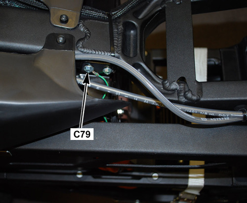
Version 1
|
C90 Brushless Motor Controller |
||
|
19332
|
||
|
Connector Part Information |
|
|
|
Pin |
Wire Color |
Function |
| 1 | ORN/RED | Voltage From Key Switch |
| 2 | BLU | CAN Termination |
| 3-5 | — | Not Used |
| 6 | ORN/RED | Voltage From Key Switch |
| 7-14 | — | Not Used |
| 15 | BLK | Encoder Power Supply (–) |
| 16 | WHT/GRY | CAN High |
| 17 | — | Not Used |
| 18 | ORN/GRY | Digital Input 1 |
| 19-20 | — | Not Used |
| 21 | BLU | Digital Input 8 |
| 22 | BRN | Throttle Sensor 1 Signal |
| 23 | BRN/RED | Throttle Sensor 1 Signal |
| 24 | BLU | CAN Low |
| 25 | — | Not Used |
| 26 | RED | Encoder Power Supply (+) |
| 27 | BLU/GRY | CAN Low |
| 28 | YEL/RED | CAN Power Supply (+) |
| 29 | — | Not Used |
| 30 | GRY/ORN | Digital Input 2 (Idle Switch) |
| 31-32 | — | Not Used |
| 33 | WHT | Temperature Sensor Input |
| 34 | — | Not Used |
| 35 | WHT | COSINE Input |

| Right Side of the Frame, Next to the Brushless Motor Controller |
|
com1462
Loading image...
|
Version 1
|
C97 Brushless Motor Controller Connector View |
||
|
con0051
Loading image...
|
||
|
Connector Part Information |
|
|
|
Pin |
Wire Color |
Function |
| — | BLK (Orange Sleeve Over Cable) | Fused Negative (-) Front Power Pack |
| — | BLK (Orange Sleeve Over Cable) | Fused Negative (-) Rear Power Pack |
| Front of the Frame, Below the Front Power Pack |
|
com1467
Loading image...
|
Version 1
|
C113 Brushless Motor Controller |
||
|
con0051
Loading image...
|
||
|
Connector Part Information |
|
|
|
Pin |
Wire Color |
Function |
| — | BLK (Orange Sleeve Over Cable) | M1 Going to the Motor |
| Front of the Frame, Below the Front Power Pack |
|
com2006
Loading image...
|
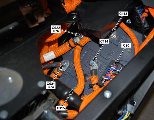
Version 1
|
C114 Brushless Motor Connector |
||
|
con0051
Loading image...
|
||
|
Connector Part Information |
|
|
|
Pin |
Wire Color |
Function |
| — | BLK (Orange Sleeve Over Cable) | Going to the Motor |
| Front of the Frame, Below the Front Power Pack |
|
com2006
Loading image...
|
Version 1
|
C115 Brushless Motor Connector |
||
|
con0051
Loading image...
|
||
|
Connector Part Information |
|
|
|
Pin |
Wire Color |
Function |
| — | BLK (Orange Sleeve Over Cable) | Going to the Motor |
| Front of the Frame, Below the Front Power Pack |
|
com2006
Loading image...
|
Version 1
|
C137 Power Pack (Front) Signal |
||
|
con0911
|
||
|
Connector Part Information |
|
|
|
Pin |
Wire Color |
Function |
| P1 | ORN | Low Power B+ |
| P2 | RED | CAN 5 Volts |
| P3 | — | Not Used |
| P4 | YEL/GRY | 12 Volt Output |
| P5 | WHT | CAN High |
| P6 | — | Not Used |
| P7 | GRY/BRN | Node ID 1 |
| P8 | GRY/BRN | Ground |
| S1 | BRN | System ON Reference |
| S2 | BLK | CAN Ground |
| S3 | BRN/WHT | System ON |
| S4 | BLU | CAN Low |
| S5 | PNK | Loopback Output (HVIL) |
| S6 | GRN/YEL | Chassis Ground |
| S6 | GRN/YEL | Chassis Ground |
| S7 | PNK | Loopback Return (HVIL) |
| S8 | BLK/WHT | Throttle Enable |
| Center of the Frame, Between the Power Packs |
|
com1468
Loading image...
|
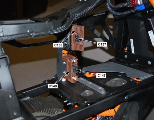
Version 1
|
C138 Front Power Pack Connector Face View |
||
|
con0912
|
||
|
Connector Part Information |
|
|
|
Pin |
Wire Color |
Function |
| 1 | BLK | Battery Positive (+) |
| 2 | BLK | Battery Positive (-) |

| Center of the Frame, Between the Power Packs |
|
com1468
Loading image...
|
Version 1
|
CON0871
Loading image...
|
|||||||
| Connector Part Information |
|
Connector Part Information |
|
||||
| Pin | Wire Color | Function | Pin | Wire Color | Function | ||
| 1 | BLK | Ground 12V | 1 | BLK | Ground 12V | ||
| 2 | BLK | Ground 12V | 2 | BLK | Ground 12V | ||
| 3 | BLU/GRN | HCU Voltage | 3 | BLU/GRN | HCU Voltage | ||
| 4 | BLU/ORN | Pump Voltage | 4 | BLU/ORN | Pump Voltage | ||
| Front Right Side of the Frame, Behind the Right Fairing Panel |
|
com1905
Loading image...
|

Version 1
|
C147 Power Pack (Rear) Signal Connector Face View |
||
|
con0910
|
||
|
Connector Part Information |
|
|
|
Pin |
Wire Color |
Function |
| P1 | ORN ORN ORN |
Low Power B+ |
| P2 | RED RED |
CAN 5 Volts |
| P3 | — | Not Used |
| P4 | YEL/GRY YEL/GRY |
12 Volt Output |
| P5 | WHT WHT |
CAN High |
| P6 | GRY/BLK | Node ID 0 |
| P7 | GRY/BLK | Node ID 1 |
| P8 | GRY/BLK GRY/BLK |
Ground |
| S1 | BRN BRN |
System ON Reference |
| S2 | BLK BLK |
CAN Ground |
| S3 | BRN/WHT BRN/WHT |
System ON |
| S4 | BLU BLU |
CAN Low |
| S5 | PNK | Loopback Output (HVIL) |
| S6 | GRN/YEL | Ground |
| S7 | PNK | Loopback Input (HVIL) |
| S8 | BLK/WHT BLK/WHT |
Throttle Enable |
| Center of the Frame, Between the Power Packs |
|
com1468
Loading image...
|
Version 1
|
C148 Rear Power Pack Connector Face View |
||
|
con0909
|
||
|
Connector Part Information |
|
|
|
Pin |
Wire Color |
Function |
| 1 | BLK | Battery Positive (+) |
| 2 | BLK | Battery Positive (-) |
| Center of the Frame, Between the Power Packs |
|
com1468
Loading image...
|
Version 1
|
C207 Charger Fuse |
||
|
con0770
|
||
|
Connector Part Information |
|
|
|
Pin |
Wire Color |
Function |
| 1 | ORN | Low Voltage (+) Input |
| 2 | ORN | Low Voltage (+) Output |

| Right Front of Frame, Under Front Power Pack, Inside the Harness |
|
com1475
Loading image...
|
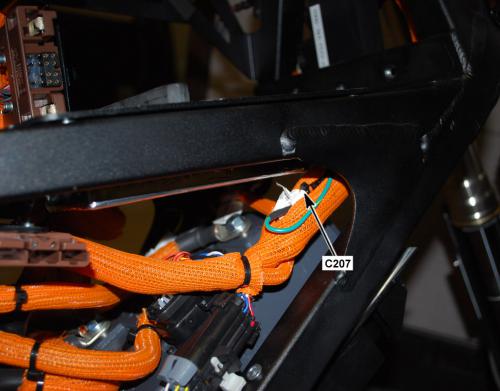
Version 1
|
C238 Equipment Ground (Fork) |
||
|
con0050
|
||
|
Connector Part Information |
|
|
|
Pin |
Wire Color |
Function |
| — | BLK | Ground |
| Under the Instrument Panel, Behind the Headlight |
|
com1906
Loading image...
|

Version 1
|
C239 Equipment Ground (Frame) |
||
|
con0050
|
||
|
Connector Part Information |
|
|
|
Pin |
Wire Color |
Function |
| — | BLK | Ground |
| Right Side of the Frame, Behind the Fuse Center (Harness Moved for Clarity) |
|
com1908
Loading image...
|

Version 1
|
18510
Loading image...
|
|||||||
| Connector Part Information |
|
Connector Part Information |
|
||||
| Pin | Wire Color | Function | Pin | Wire Color | Function | ||
| 1 | — | Not Used | 1 | LT BLU | Not Used | ||
| 2 | — | Not Used | 2 | BRN | Not Used | ||
| 3 | YEL/GRY | Key Switch Ground | 3 | RED | Key Switch Ground | ||
| 4 | YEL/GRN | Key Switch Signal | 4 | RED/BLK | Key Switch Signal | ||

| Front Right Side of the Frame, Behind the Right Fairing Panel |
|
com1905
Loading image...
|
Version 1
|
con0753
Loading image...
|
|||||||
| Connector Part Information |
|
Connector Part Information |
|
||||
| Pin | Wire Color | Function | Pin | Wire Color | Function | ||
| 1 | BLU/BLK | Start Switch Signal | 1 | BLK | Start Switch Signal | ||
| 2 | RED | Switch 5 Volts | 2 | BLU/WHT | Switch 5 Volts | ||
| 3 | RED | Motor Stop Switch Output 5 Volts | 3 | RED/WHT | Motor Stop Switch Output 5 Volts | ||
| 4 | RED/BLK | Motor Stop Switch Input | 4 | RED/WHT | Motor Stop Switch Input | ||

| Under the Instrument Panel, Behind the Fly-Screen |
|
com1906
Loading image...
|
Version 1
|
CON0752
Loading image...
|
|||||||
| Connector Part Information |
|
Connector Part Information |
|
||||
| Pin | Wire Color | Function | Pin | Wire Color | Function | ||
| 1 | YEL/BLK | Warning Light Control (red) | 1 | YEL/BLK | Warning Light Control (red) | ||
| 2 | YEL | Temperature Light Control (amber) | 2 | YEL | Temperature Light Control (amber) | ||
| 3 | RED/WHT | Armed Light Control (green) | 3 | GRN | Armed Light Control (green) | ||
| 4 | VIO | Charge LED Light Control (green) | 4 | WHT/BLK | Charge LED Light Control (green) | ||
| 5 | WHT/BLU | Check Engine Light Control | 5 | BLU | Check Engine Light Control | ||
| 6 | RED/BLK | High Beam Indicator Control (blue) | 6 | BRN/BLK | High Beam Indicator Control (blue) | ||
| 7 | GRN | Left Turn Indicator Control (green) | 7 | GRN | Left Turn Indicator Control (green) | ||
| 8 | GRY | Right Turn Indicator Control (green) | 8 | GRY | Right Turn Indicator Control (green) | ||
| 9 | BLK | Ground 12 Volt | 9 | BLK | Ground 12 Volt | ||
| 10 | RED | State of Charge Control (5 Volt) | 10 | PNK | State of Charge Control (5 Volt) | ||
| 11 | WHT | CAN 2 High | 11 | WHT | CAN 2 High | ||
| 12 | BLU | CAN 2 Low | 12 | BLU | CAN 2 Low | ||
| 13 | ORN/BLK | CAN 2 5 Volts | 13 | ORN/BLK | CAN 2 5 Volts | ||
| 14 | BLU/WHT | ABS | 14 | GRY | ABS | ||
| 15 | ORN | Charge LED Light Control (red) | 15 | ORN | Charge LED Light Control (red) | ||
| 16 | BRN | 12 Volt Feed | 16 | BRN | 12 Volt Feed | ||
| 17-20 | — | Not Used | 17-20 | — | Not Used | ||
| Front Right Side of the Frame, Behind the Fairing Panel |
|
com1905
Loading image...
|
Version 1
|
C286 Low Beam Headlight Connector Face View |
|||
|
con0758
Loading image...
|
|||
|
Connector Part Information |
|
||
| Pin | Wire Color | Function | |
| 1 | RED/YEL |
Low Beam Control |
|

|
con0758
Loading image...
|
|||
|
Connector Part Information |
|
||
| Pin | Wire Color | Function | |
| 2 | BLK |
Low Beam Ground |
|
| Behind the Headlight Assembly |
|
com1470
Loading image...
|

Version 1
|
C287 High Beam Headlight Connector Face View |
|||
|
con0758
Loading image...
|
|||
|
Connector Part Information |
|
||
| Pin | Wire Color | Function | |
| 1 | RED/BLK |
High Beam Control |
|
|
con0758
Loading image...
|
|||
|
Connector Part Information |
|
||
| Pin | Wire Color | Function | |
| 2 | BLK |
High Beam Ground |
|
| Behind the Headlight Assembly |
|
com1470
Loading image...
|
Version 1
|
C296 Brushless Motor Controller |
|||
|
con0051
Loading image...
|
|||
|
Connector Part Information |
|
||
| Pin | Wire Color | Function | |
| — | BLK (Orange Sleeve Over Cable |
Positive (+) Front Power Pack |
|
| — | BLK (Orange Sleeve Over Cable |
Positive (+) Rear Power Pack |
|
| Front of the Frame, Below the Front Power Pack |
|
com1467
Loading image...
|
Version 1
|
C318 12 Volt Accessory |
||
|
con0749
|
||
|
Connector Part Information |
|
|
|
Pin |
Wire Color |
Function |
| 1 | BLK | Ground, Accessory 0 V |
| 2 | BLU | Fuse 2 Voltage |

| Front Right Side of the Frame, Behind the Right Fairing Panel |
|
com1903
Loading image...
|

Version 1
|
C428 ABS HCU Connector Face View |
||
|
con0869
|
||
|
Connector Part Information |
|
|
|
Pin |
Wire Color |
Function |
| 1 | BLK | Ground |
| 2 | WHT | CAN |
| 3 | BLK/WHT | Front Wheel Speed Sensor (WSS) |
| 4 | BLU/ORG | Fuse 1 Voltage |
| 5-8 | — | Not Used |
| 9 | BLU/GRN | Fuse 2 Voltage |
| 10 | BLK | Motor Ground |
| 11 | BLU | CAN |
| 12 | BLK/RED | Front Wheel Speed Sensor (WSP) |
| 13 | BLK/RED | Rear Wheel Speed Sensor (WSP) |
| 14 | BLK/WHT | Rear Wheel Speed Sensor (WSS) |
| 15 | BLK/GRY | OFF Output |
| 16 | — | Not Used |
| 17 | BLK/GRN | Indicator Control Output |
| 18 | BLU/ORG | In-Line Fuse (ABS Pump) |
| Left Front of the Frame, Above the Front Battery Pack |
|
com1904
Loading image...
|
Version 1
|
C429 Front Wheel Speed Sensor Connector Face View |
||
|
con0462
|
||
|
Connector Part Information |
|
|
|
Pin |
Wire Color |
Function |
| 1 | BLK/RED | WSP |
| 2 | BLK/WHT | WSS |

| Above the Headlight, Behind the Fly-Screen |
|
com1906
Loading image...
|
Version 1
|
C430 Rear Wheel Speed Sensor Connector Face View |
||
|
con0462
|
||
|
Connector Part Information |
|
|
|
Pin |
Wire Color |
Function |
| 1 | BLK/RED | WSP |
| 2 | BLK/WHT | WSS |
| Under the Seat, Above the Front Power Pack |
|
com1904
Loading image...
|
Version 1
|
C429 Front Wheel Speed Sensor Connector Face View |
||
|
con0462
|
||
|
Connector Part Information |
|
|
|
Pin |
Wire Color |
Function |
| 1 | BLK/RED | WSP |
| 2 | BLK/WHT | WSS |

| Above the Headlight, Behind the Fly-Screen |
|
com1906
Loading image...

|

Version 1
|
C430 Rear Wheel Speed Sensor Connector Face View |
||
|
con0462
|
||
|
Connector Part Information |
|
|
|
Pin |
Wire Color |
Function |
| 1 | BLK/RED | WSP |
| 2 | BLK/WHT | WSS |
| Under the Seat, Above the Front Power Pack |
|
com1904
Loading image...
|

Version 1
|
con0756
Loading image...
|
|||||||
| Connector Part Information |
|
Connector Part Information |
|
||||
| Pin | Wire Color | Function | Pin | Wire Color | Function | ||
| 1 | BRN | Running Light Control | 1 | BRN | Running Light Control | ||

|
con0756
Loading image...
|
|||||||
| Connector Part Information |
|
Connector Part Information |
|
||||
| Pin | Wire Color | Function | Pin | Wire Color | Function | ||
| 2 | BLK | Running Light Ground | 2 | GRN | Running Light Ground | ||
| Behind the Headlight Assembly |
|
com1906
Loading image...
|
Version 1
|
C432A Front Running Light |
||
|
18077
|
||
|
Connector Part Information |
|
|
|
Pin |
Wire Color |
Function |
| 1 | GRN | Running Lamp Ground |
| 2 | BRN | Running Lamp Supply Voltage |

| Bottom of the Headlight |
|
com1485
Loading image...
|

Version 1
|
con0756
Loading image...
|
|||||||
| Connector Part Information |
|
Connector Part Information |
|
||||
| Pin | Wire Color | Function | Pin | Wire Color | Function | ||
| 1 | BRN | Running Light Control | 1 | BRN | Running Light Control | ||
|
con0756
Loading image...
|
|||||||
| Connector Part Information |
|
Connector Part Information |
|
||||
| Pin | Wire Color | Function | Pin | Wire Color | Function | ||
| 2 | BLK | Running Light Ground | 2 | GRN | Running Light Ground | ||
| Behind the Headlight Assembly |
|
com1906
Loading image...
|
Version 1
|
C433A Front Running Light |
||
|
18077
|
||
|
Connector Part Information |
|
|
|
Pin |
Wire Color |
Function |
| 1 | GRN | Running Lamp Ground |
| 2 | BRN | Running Lamp Supply Voltage |
| Bottom of the Headlight |
|
com1485
Loading image...
|
Version 1
|
CON0870
Loading image...
|
|||||||
| Connector Part Information |
|
Connector Part Information |
|
||||
| Pin | Wire Color | Function | Pin | Wire Color | Function | ||
| A | BLU | CAN 2 Low | A | BLU | CAN 2 Low | ||
| B | BLK/GRY | ABS Off | B | BLK/GRY | ABS Off | ||
| C | BLK | 12V Ground | C | — | Not Used | ||
| D | WHT/BLU | CAN 2 High | D | WHT | CAN 2 High | ||
| E | BLK/GRN | ABS Lamp | E | BLK/GRN | ABS Lamp | ||
| F | BLU/ORN | HCU Voltage | F | BLU/ORN | HCU Voltage | ||
| Front Right Side of the Frame, Behind the Fairing Panel |
|
com1905
Loading image...
|
Version 1
|
CON0908
Loading image...
|
|||||||
| Connector Part Information |
|
Connector Part Information |
|
||||
| Pin | Wire Color | Function | Pin | Wire Color | Function | ||
| 1 | BLU/RED | Sensor 2 Voltage 5V | 1 | BLK | Sensor 2 Voltage 5V | ||
| 2 | BRN/RED | Sensor 2 Signal | 2 | BLU | Sensor 2 Signal | ||
| 3 | ORN/BLK | Ground | 3 | WHT | Ground | ||
| 4 | — | Not Used | 4 | BRN | Not Used | ||
| 5 | ORN/BLK | Ground | 5 | ORN | Ground | ||
| 6 | BRN | Sensor 1 Signal | 6 | RED | Sensor 1 Signal | ||
| 7 | BLU/BRN | Sensor 1 Voltage 5V | 7 | YEL | Sensor 1 Voltage 5V | ||
| 8 | GRY/ORN | Idle Switch | 8 | GRN | Idle Switch | ||
| Above the Headlight, Behind the Fly-Screen |
|
com1906
Loading image...
|
Version 1
|
D11 Inline Temperature Sensor |
||
|
Image Not Available
|
||
|
Pin |
Wire Color |
Function |
| 1 | BLK | Temperature Sensor 1 Input |
| 2 | BLK | Ground |
| Left Side of the Frame, Next to the Data Link Connector (DLC) |
|
COM1907
Loading image...
|
Version 1
|
D143 ABS Pump Inline Fuse |
||
|
Image Not Available
|
||
|
Connector Part Information |
|
|
|
Pin |
Wire Color |
Function |
|
1 |
BLU |
Voltage from DC/DC Converter |
|
2 |
BLU/ORN |
Voltage to ABS HCU Converter |
| Under the Right Side Fairing Panel, Above the Front Power Pack |
|
com1902
Loading image...
|

Version 1
|
D317 Charger Fuse |
||
|
con0051
Loading image...

|
||
|
Connector Part Information |
|
|
|
Pin |
Wire Color |
Function |
| 1 | BLK (Orange Sleeve Over Cable) | Positive (+) Output |
|
con0051
Loading image...
|
||
|
Connector Part Information |
|
|
|
Pin |
Wire Color |
Function |
| 2 | BLK (Orange Sleeve Over Cable) | Battery Positive (+) Input |
| Above the Brushless Motor Controller, In Front of the Motor (Part of the Cable) |
|
com1668
Loading image...
|

Version 1
Left Side of the Frame, Above the Front Power Pack
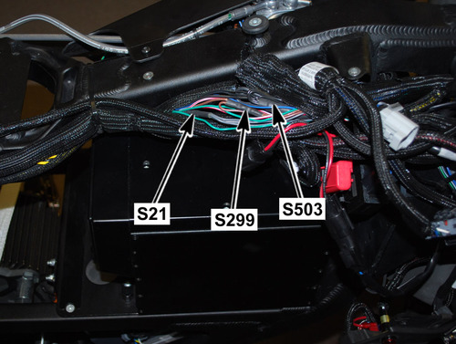
|
Joint |
Connector |
Pin |
Color |
Function |
|
Loading image...
|
C35 | 8 | GRY | Right Turn Signal Input |
|
Loading image...
|
C282 | 8 | GRY | Right Turn Signal Output |
|
Loading image...
|
C36 | 3 | GRY | Right Turn Signal Output |
|
Loading image...
|
C34 | 1 | GRY | Right Turn Signal Output |
Version 1
Right Side of the Frame, Under the Seat
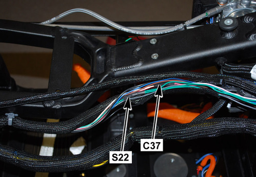
|
Joint |
Connector |
Pin |
Color |
Function |
|
Loading image...
|
C35 | 10 | GRN | Left Turn Signal Input |
|
Loading image...
|
C282 | 7 | GRN | Left Turn Signal Output |
|
Loading image...
|
C36 | 1 | GRN | Left Turn Signal Output |
|
Loading image...
|
C33 | 1 | GRN | Left Turn Signal Output |
Version 1
Left Side of the Frame, Next to the 12 Volt Fuse Center
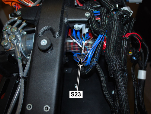
|
Joint |
Connector |
Pin |
Color |
Function |
|
Loading image...
|
C8 | 2 | BLU | 12 Volt Input |
|
Loading image...
|
C46 | 1 | BLU | 12 Volt Output |
|
Loading image...
|
C46 | 2 | BLU | 12 Volt Output |
|
Loading image...
|
C46 | 3 | BLU | 12 Volt Output |
| C46 | 4 | BLU | 12 Volt Output | |
| C46 | 5 | BLU | 12 Volt Output | |
| C1 | 4 | BLU | 12 Volt Output | |
| C143 | 1 | BLU | 12 Volt Output |
Version 1
Left Side of the Frame, Next to the Fuse Center
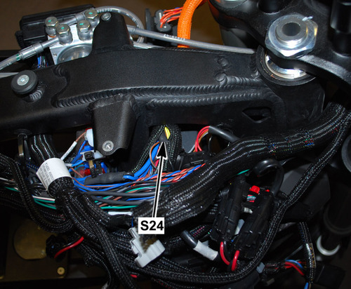
|
Joint |
Connector |
Pin |
Color |
Function |
|
Loading image...
|
C8 | 1 | BLK | 12 Volt Ground Input |
|
Loading image...
|
S257 | — | BLK | 12 Volt Ground Output |
|
Loading image...
|
C1 | 29 | BLK | 12 Volt Ground Output |
|
Loading image...
|
C282 | 9 | BLK | 12 Volt Ground Output |
|
Loading image...
|
C3 | 4 | BLK/BLU | 12 Volt Ground Output |
Version 1
Front of the Motorcycle, Under the Instrument Panel
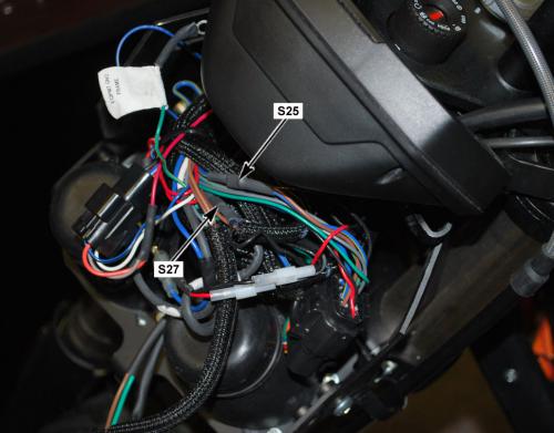
|
Joint |
Connector |
Pin |
Color |
Function |
|
Loading image...
|
C46 | 10 | BLU/YEL | 12 Volt Input (Fuse 3) |
|
Loading image...
|
C35 | 5 | BLU/YEL | High/Low Beam Headlight |
|
Loading image...
|
C35 | 2 | BRN | Flash to Pass |
Version 1
Front of the Motorcycle, Under the Instrument Panel
|
Joint |
Connector |
Pin |
Color |
Function |
|
Loading image...
|
C46 | 8 | BLU/BLK | 12 Volt Input (fuse 5) |
|
Loading image...
|
C38 | 1 | BLU/BLK | Foot Brake Light Switch |
|
Loading image...
|
C45 | 1 | BLU/BLK | Hand Brake Light Switch |
|
Loading image...
|
C42 | 1 | BLU/BLK | Turn Signal Flasher |
|
Loading image...
|
C32 | 2 | BLU/BLK | Horn |
Version 1
Left Side of the Frame, Next to the Fuse Center
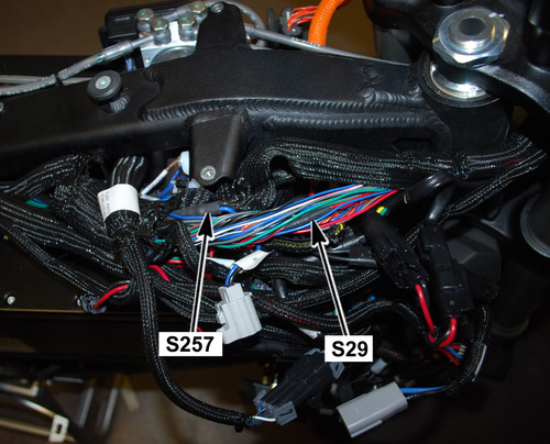
|
Joint |
Connector |
Pin |
Color |
Function |
|
Loading image...
|
C35 | 4 | RED/BLK | Headlight Switch Output |
|
Loading image...
|
C287 | 1 | RED/BLK | Headlight Switch Output |
|
Loading image...
|
C282 | 6 | RED/BLK | I/P High Beam Indicator Control Input |
Version 1
Right Side of the Frame, Under the Seat
|
Joint |
Connector |
Pin |
Color |
Function |
|
Loading image...
|
C45 | 2 | WHT/RED | Hand Brake Light Switch Output |
|
Loading image...
|
C36 | 5 | WHT/RED | Brake Light Input |
|
Loading image...
|
C38 | 2 | WHT/RED | Foot Brake Light Switch Output |
|
Loading image...
|
C1 | 28 | WHT/RED | Brake Light Switch Input |
Version 1
Right Side of the Frame, Next to the Brushless Motor Controller Connector
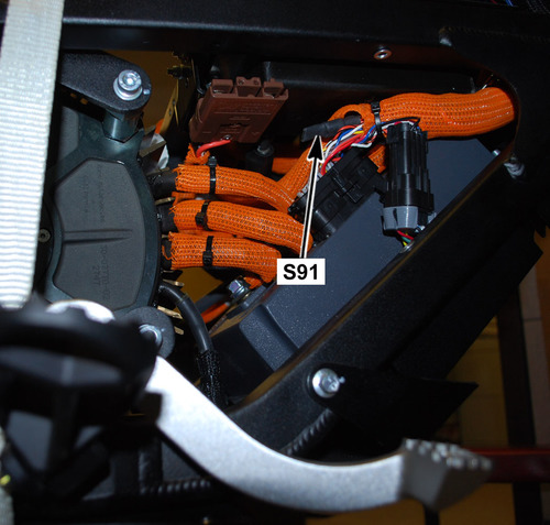
|
Joint |
Connector |
Pin |
Color |
Function |
|
Loading image...
|
C76 | 1 | ORN/BLK | Brushless Motor Controller (ground) |
|
Loading image...
|
C2 | 1 | ORN/BLK | Main Bike Board (MBB) |
|
Loading image...
|
C1 | 7 | ORN/BLK | Main Bike Board (MBB) |
|
Loading image...
|
C14 | G | ORN/BLK | Motor |
|
Loading image...
|
C459 | 3 | ORN/BLK | Throttle |
|
Loading image...
|
C459 | 5 | ORN/BLK | Throttle |
|
Loading image...
|
C8 | 3 | ORN/BLK | DC/DC Converter |
|
Loading image...
|
C57 | 3 | ORN/BLK | Charger |
|
Loading image...
|
C57 | 14 | ORN/BLK | Charger |
Version 1
Below the Front Power Pack, In Front of the Motor
Photo Not Available
|
Joint |
Connector |
Pin |
Color |
Function |
|
Loading image...
|
C97 | — | BLK (Orange Sleeve Over Cable) | Brushless Motor Controller Negative (-) |
|
Loading image...
|
C138 | 2 | BLK (Orange Sleeve Over Cable) | Front Power Pack Negative (-) |
|
Loading image...
|
C148 | 2 | BLK (Orange Sleeve Over Cable) | Rear Power Pack Negative (-) |
Version 1
Left Side of the Frame, Next to the Fuse Center
|
Joint |
Connector |
Pin |
Color |
Function |
|
Loading image...
|
S24 | - | BLK | 12 Volt Ground Input |
|
Loading image...
|
C36 | 4 | BLK | 12 Volt Ground Output |
|
Loading image...
|
C36 | 6 | BLK | 12 Volt Ground Output |
|
Loading image...
|
C457 | C | BLK | 12 Volt Ground Output |
|
Loading image...
|
C142 | 1 | BLK | 12 Volt Ground Output |
|
Loading image...
|
C142 | 2 | BLK | 12 Volt Ground Output |
|
Loading image...
|
C36 | 2 | BLK | 12 Volt Ground Output |
|
Loading image...
|
C42 | 3 | BLK | 12 Volt Ground Output |
|
Loading image...
|
C26 | 2 | BLK | 12 Volt Ground Output |
|
Loading image...
|
C318 | 1 | BLK | 12 Volt Ground Output |
|
Loading image...
|
S503 | - | BLK | 12 Volt Ground Output |
Version 1
Left Side of the Frame, Above the Front Power Pack
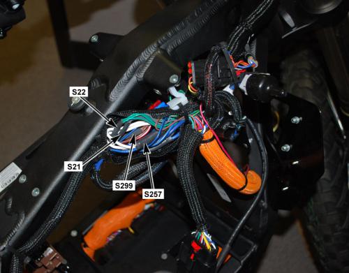
|
Joint |
Connector |
Pin |
Color |
Function |
|
Loading image...
|
C46 | 7 | BRN | Fuse 4 Output |
|
Loading image...
|
C36 | 7 | BRN | Tail Light 12 Volts |
|
Loading image...
|
C432 | 1 | BRN | Front Running Light 1 12 Volts |
|
Loading image...
|
C282 | 16 | BRN | Instrument Panel 12 Volts |
|
Loading image...
|
C433 | 1 | BRN | Front Running Light 2 12 Volts |
Version 1
Below the Front Power Pack, Across from the Main Bike Board

|
Joint |
Connector |
Pin |
Color |
Function |
|
Loading image...
|
C2 | 6 | WHT | Main Bike Board CAN High Output |
|
Loading image...
|
C57 | 7 | WHT | Charger |
|
Loading image...
|
C282 | 11 | WHT | Instrument Panel |
Version 1
Below the Front Power Pack, Across from the Main Bike Board
|
Joint |
Connector |
Pin |
Color |
Function |
|
Loading image...
|
C2 | 7 | BLU | Main Bike Board CAN Low Output |
|
Loading image...
|
C57 | 6 | BLU | Charger |
|
Loading image...
|
C282 | 12 | BLU | Instrument Panel |
Version 1
Left Side of the Frame, Above the Front Power Pack
|
Joint |
Connector |
Pin |
Color |
Function |
|
Loading image...
|
S257 | - | BLK | 12 Volt Ground Input |
|
Loading image...
|
C433 | 2 | BLK | 12 Volt Ground Output |
|
Loading image...
|
C432 | 2 | BLK | 12 Volt Ground Output |
|
Loading image...
|
C286 | 2 | BLK | 12 Volt Ground Output |
|
Loading image...
|
C287 | 2 | BLK | 12 Volt Ground Output |
|
Loading image...
|
C35 | 7 | BLK/WHT | 12 Volt Ground Output |
|
Loading image...
|
C33 | 2 | BLK | 12 Volt Ground Output |
|
Loading image...
|
C34 | 2 | BLK | 12 Volt Ground Output |
Version 1
| Front of the Frame, Below the Front Power Pack |
|
com1694
Loading image...
|

Version 1
| Back of the Frame, Below the Rear Power Pack |
|
com1694
Loading image...
|
Version 1
| Back of the Frame, Below the Rear Power Pack |
|
com1694
Loading image...

|
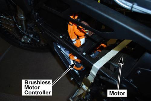
Version 1
| Under the Cover, Below the Front Power Pack |
|
com1695
Loading image...
|
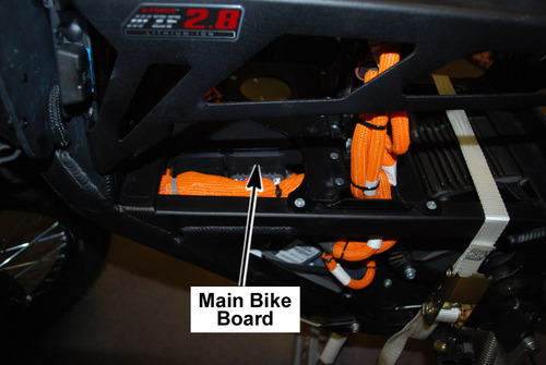
Version 1
| Torque settings for: ABS Harness Replacement (except 11kW) | |
| Item | Torque Setting |
| Seat Bolts | 15 N•m (11 lb in) |
| Front Fairing Screws | 2.7 N•m (24 lb in) |
| Fly-screen Screws | 2.7 N•m (24 lb in) |
 Show Torque Table
Caution: Always perform the High Voltage Discharging procedure prior to servicing any High Voltage component or connection. Proper procedures must be followed.
Required Tools
• 3mm hex wrench
• 5mm hex wrench
• PN 85-05665 Controller Discharge Tool
Fastener Torques
• Seat bolts 15 N•m (11 lb ft)
• Front fairing screws 2.7 N•m (24 lb in)
• Fly-screen screws 2.7 N•m (24 lb in)
Removal Procedure
Caution: Refer to High Voltage Caution in General Information.
Note routing and location of harness and zip tie.
1. Discharge the High Voltage system. Refer the the High Voltage Discharging.
2. Remove the power packs.
3. Remove the fly-screen.
4. Remove the seat.
5. Remove the both right and left fairing panels.
6. Disconnect C428 ABS HCU connector.
7. Disconnect C429 front wheel speed sensor connector.
8. Disconnect C430 rear wheel speed sensor connector.
9. Disconnect C142/C431 inline connector (chassis harness to ABS harness).
10. Disconnect C457/C472 inline connector (chassis harness to ABS harness).
Note harness routing prior to removal; this will aid in reassembly of the harness to the motorcycle.
11. Release all main wiring harness zip ties and hold down brackets and remove the harness.
Installation Procedure
1. Layout the wiring harness in the sam elocation as removed on the frame.
2. Connect C457/C472 inline connector (chassis harness to ABS harness).
3. Connect C142/C431 inline connector (chassis harness to ABS harness).
4. Connect C430 rear wheel speed sensor connector.
5. Connect C429 front wheel speed sensor connector.
6. Connect C428 ABS HCU connector.
7. Install both right and left fairing panels.
Tighten
Fairing panel screws to 2.7 N•m (24 lb in)
8. Install the seat.
Tighten
Seat bolt to 15 N•m (11 lb ft)
9. Install the fly-screen. Ensure that ground C238 is between the fly-screen bolt and the bracket.
Tighten
Fly-screen screw to 2.7 N•m (24 lb in)
10. Install the power packs.
Version 1
Caution: Always perform the High Voltage Discharging procedure prior to servicing any High Voltage component or connection. Proper procedures must be followed.
Failure to follow the procedures may result in serious injury or death.
• Always verify that the high voltage has been discharged before working on or around high voltage components, wires, cables, or harnesses.
• Remove all metal objects such as rings and watches.
• Always tighten the high voltage terminal fasteners to the specified torque. Insufficient or excessive torque will cause malfunctions or damage.
• After finishing work on the high voltage system and before turning the key ON.
o Verify high voltage system integrity and that all connectors and covers are installed.
o Verify that all tools or loose components have been removed.
Caution: Exposure to high voltage can cause shock, burns, and even death. The high voltage components on the motorcycle should only be serviced by technicians familiar with the circuit/system operation. Refer to System Description and Operation.
High voltage components are identified by labels. Do not remove, open, take apart, or modify these components. High voltage cable or wiring has orange covering. Do not probe, tamper with, cut, or modify high voltage cable or wiring.
Required Tools
PN 85-05665 Controller Discharge Tool
1. Review the High Voltage System Description and Operation.
2. Remove the key from the key switch.
3. Remove the fasteners in the upper rear corner of the right lower rubber cover.
4. Clean any dirt or debris away from the quick charge connector.
5. Plug the Controller Discharge Tool (1) into the quick charge connector, allow 30 seconds for the capacitors to discharge. Note: the bulb may or may not light up pending on the amount of strained voltage in the brushless motor controllers capacitors.
Version 1
| Torque settings for: Instrument Panel Replacement | |
| Item | Torque Setting |
| Instrument Panel Nut | 4 N•m (36 lb in) |
| Front Fairing Screws | 2.7 N•m (24 lb in) |
| Fly-screen Screws | 2.7 N•m (24 lb in) |
Show Torque Table
Required Tools
• 3mm hex wrench
• 10mm wrench or socket
• Socket wrench
Fastener Torques
• Instrument panel nuts 4 N•m (36 lb in)
• Front fairing screws 2.7 N•m (24 lb in)
• Fly-screen screws 2.7 N•m (24 lb in)
Removal Procedure
1. Remove the fly-screen.
2. Remove the right fairing panel.
3. Disconnect the instrument panel harness connector C282. Note the location of the zip ties for reassembly.
4. Remove and discard the zip ties.
5. Remove the 2 nuts (1) securing the instrument panel to the bracket, remove the instrument panel.
Installation Procedure
Notice: Refer to Fastener Notice in General Information
1. Install the 2 nuts (1) securing the instrument panel to the turn signal brackets.
Tighten
Instrument Panel nuts to 4 N•m (36 lb in)
2. Connect the instrument panel harness connector C282.
3. Turn the handlebar fully right and install new zip ties in the same location as removed.
4. Install the fly-screen. Ensure that ground C238 is between the fly-screen bolt and the bracket.
Tighten
Fly-screen screws to 2.7 N•m (24 lb in)
5. Install the right fairing panel.
Tighten
Front fairing screws to 2.7 N•m (24 lb in)
Version 1
| Torque settings for: Main Chassis Harness Replacement (11kW) | |
| Item | Torque Setting |
| Front Fender Bolts | 2 N•m (22 lb in) |
| Seat Bolts | 15 N•m (11 lb ft) |
| Brushless Motor Controller Bolt | 11 N•m (8 lb ft) |
| Front Fairing Screws | 2.7 N•m (24 lb in) |
| Fly-screen Screws | 2.7 N•m (24 lb in) |
Show Torque Table
Caution: Always perform the High Voltage Discharging procedure prior to servicing any High Voltage component or connection. Proper procedures must be followed.
Required Tools
• 3mm hex wrench
• 5mm hex wrench
• 7mm socket
• 10mm socket
• Socket wrench
• 13mm wrench
• Philips screw driver
• PN 85-05665 Controller Discharge Tool
Fastener Torques
• Brushless motor controller cable bolt 11 N•m (8 lb ft)
• Seat bolts 15 N•m (11 lb ft)
• Fly-screen screws 2.7 N•m (24 lb in)
• Front fairing screws 2.7 N•m (24 lb in)
• Front fender bolts 2.7 N•m (24 lb in)
Removal Procedure
Caution: Refer to High Voltage Caution in General Information
Note routing and location of harness and zip tie.
1. Disable the High Voltage system. Refer to High Voltage Discharging.
2. Remove the fly-screen.
3. Remove the seat.
4. Remove the front fender.
5. Remove the fairing assembly (FAIRING FRONT RIGHT POLYPROPOLENE BLACK, FAIRING FRONT LEFT POLYPROPOLENE BLACK, XMX FAIRING CENTER).
6. Remove the upper brushless motor controller bracket.
7. Remove the lower rubber side covers (XMX CONTROLLER COVER L, XMX CONTROLLER COVER R).
8. Remove the C137 from the power pack connector body.
9. Disconnect C1 and C2 main bike board connectors.
10. Disconnect C10 kickstand switch connector.
11. Disconnect C57 charger connector.
12. Remove the C3 data link connector fasteners.
13. Disconnect C8 DC/DC converter connector.
14. Disconnect C14 motor harness connector.
15. Remove C76 ground eyelet from the brushless motor controller.
16. Disconnect the C90 brushless motor controller connector.
17. Remove the C50 quick charge connector bracket.
18. Remove C74 positive eyelet from the brushless motor controller.
19. Disconnect C274 key switch connector.
20. Disconnect C42 turn signal flasher connector.
21. Disconnect C459 throttle connector.
22. Disconnect C282 instrument panel connector.
23. Remove the headlight assembly, and disconnect C286, C287, C432, and C433.
24. Disconnect C275 right handlebar control connector.
25. Disconnect C33 right front turn signal connector.
26. Disconnect C34 left front turn signal connector.
27. Disconnect C35 left handlebar control connector.
28. Disconnect C32 horn connectors.
29. Disconnect C45 hand brake switch connector.
30. Disconnect C429 front wheel speed sensor.
31. Disconnect C238 ground eyelet from the frame.
32. Disconnect C428 anti-lock brake control module.
33. Remove the fuse center fasteners C46, and the ABS inline fuse fastener.
34. Disconnect C430 rear wheel speed sensor.
35. Disconnect C38 foot brake lamp switch connector.
36. Disconnect C36 inline connector (chassis harness to rear signal harness.
Note harness routing prior to removal; this will aid in reassembly of the harness to the motorcycle.
37. Release all main wiring harness zip ties and hold down brackets and remove the harness.
Installation Procedure
1. Layout the wiring harness in the same location as removed on the frame.
2. Connect C36 inline connector (chassis harness to rear signal harness.
3. Connect C38 foot brake lamp switch connector.
4. Connect C430 rear wheel speed sensor.
5. Install the fuse center and fuse center fasteners and the ABS inline fuse and fastener.
6. Connect C428 anti-lock brake control module.
7. Connect C238 ground eyelet from the frame.
8. Connect C429 front wheel speed sensor.
9. Connect C45 hand brake switch connector.
10. Connect C32 horn connectors.
11. Connect C35 left handlebar control connector.
12. Connect C34 left front turn signal connector.
13. Connect C33 right front turn signal connector.
14. Connect C275 right handlebar control connector.
15. Connect C286, C287, C432, and C433 and install the headlight assembly.
16. Connect C282 instrument panel connector.
17. Connect C459 throttle connector.
18. Connect C42 turn signal flasher connector.
19. Connect C274 key switch connector.
20. Install C74 positive eyelet onto the brushless motor controller and tighten the bolt.
Tighten
Brushless motor controller bolt to 11 N•m (8 lb ft)
21. Install the C50 quick charge connector bracket.
22. Connect the C90 brushless motor controller connector.
Notice: Refer to Fastener Notice in General Information.
23. Install C76 ground eyelet onto the brushless motor controller and tighten the bolt.
Tighten
Brushless motor controller bolt to 11 N•m (8 lb ft)
24. Connect C14 motor harness connector.
25. Connect C8 DC/DC converter connector.
26. Install the C3 data link connector fasteners.
Note: Prior to connecting the charger connector coat the terminals with CP70 dielectric grease.
27. Connect C57 charger connector.
28. Connect C10 kickstand switch connector.
29. Connect C1 and C2 main bike board connectors.
30. Install the C137 into the power pack connector body.
31. Install the zip ties in the same locations as removed.
32. Inspect harness routing to ensure that it is not in contact with any moving or sharp parts that could cause damage to the harness.
33. Install the upper brushless motor controller bracket.
34. Install the front fairing.
35. Install the front fender.
36. Install the fly-screen. Ensure that ground C239 is between the fly-screen bolt and the bracket.
37. Install the lower rubber side covers.
38. Adjust the headlight. Refer to Headlight Adjustment.
Version 1
| Torque settings for: Main Chassis Harness Replacement (except 11kW) | |
| Item | Torque Setting |
| Front Fender Bolts | 2.7 N•m (24 lb in) |
| Seat Bolts | 15 N•m (11 lb ft) |
| Brushless Motor Controller Cable Bolt | 11 N•m (8 lb ft) |
| Front Fairing Screws | 2.7 N•m (24 lb in) |
| Fly-screen Screws | 2.7 N•m (24 lb in) |
Show Torque Table
Caution: Always perform the High Voltage Discharging procedure prior to servicing any High Voltage component or connection. Proper procedures must be followed.
Required Tools
• 3mm hex wrench
• 5mm hex wrench
• 7mm socket
• 10mm socket
• Socket wrench
• 13mm wrench
• PN 85-05665 Controller Discharge Tool
Fastener Torques
• Brushless motor controller cable bolt 11 N•m (8 lb ft)
• Seat bolts 15 N•m (11 lb ft)
• Fly-screen screws 2.7 N•m (24 lb in)
• Front fairing screws 2.7 N•m (24 lb in)
• Front fender bolts 2.7 N•m (24 lb in)
Removal Procedure
Caution: Refer to High Voltage Caution in General Information
Note routing and location of harness and zip tie.
1. Disable the High Voltage system. Refer to High Voltage Discharging.
2. Remove the power packs.
3. Remove the fly-screen.
4. Remove the seat.
5. Remove the rear fender.
6. Remove the front fender.
7. Remove the fairing assembly (FAIRING FRONT RIGHT POLYPROPOLENE BLACK, FAIRING FRONT LEFT POLYPROPOLENE BLACK, XMX FAIRING CENTER).
8. Remove the upper brushless motor controller bracket.
9. Remove the lower rubber side covers (XMX CONTROLLER COVER L, XMX CONTROLLER COVER R).
10. Remove C79 ground eyelet from the frame.
11. Remove the screws securing the (1) securing the power pack connectors to the frame.
12. Remove the C137 and C147 (2) from the power pack connector body.
13. Disconnect C1 and C2 main bike board connectors.
14. Disconnect C10 kickstand switch connector.
15. Disconnect C57 charger connector.
16. Remove the C3 data link connector fasteners.
17. Disconnect C8 DC/DC converter connector.
18. Disconnect C14 motor harness connector.
19. Remove C76 ground eyelet from the brushless motor controller.
20. Disconnect the C90 brushless motor controller connector.
21. Remove the C50 quick charge connector bracket.
22. Remove C74 positive eyelet from the brushless motor controller.
23. Disconnect C274 key switch connector.
24. Disconnect C42 turn signal flasher connector.
25. Disconnect C282 instrument panel connector.
26. Disconnect C457/C472 inline connector (chassis harness to ABS harness).
27. Disconnect C142/C431 inline connector (chassis harness to ABS harness).
28. Remove the headlight assembly, and disconnect C286, C287, C432, and C433.
29. Disconnect C275 right handlebar control connector.
30. Remove the eyelet fastener for C239 ground.
31. Disconnect C33 right front turn signal connector.
32. Disconnect C34 left front turn signal connector.
33. Disconnect C35 left handlebar control connector.
34. Disconnect C45 hand brake switch connector.
35. Disconnect C459 throttle connector.
36. Disconnect C32 horn connectors.
37. Remove the fuse center fasteners, and the ABS inline fuse fastener.
38. Disconnect C38 foot brake lamp switch connector.
39. Disconnect C36 inline connector (chassis harness to signal harness).
Note harness routing prior to removal; this will aid in reassembly of the harness to the motorcycle.
40. Release all main wiring harness zip ties and hold down brackets and remove the harness.
Installation Procedure
1. Layout the wiring harness in the same location as removed on the frame.
2. Connect C36 inline connector (chassis harness to signal harness).
3. Connect C38 foot brake lamp switch connector.
4. Install the fuse center and fuse center fasteners and the ABS inline fuse and fastener.
5. Connect C32 horn connectors.
6. Connect C459 throttle connector.
7. Connect C45 hand brake switch connector.
8. Connect C35 left handlebar control connector.
9. Connect C34 left front turn signal connector.
10. Connect C33 right front turn signal connector.
11. Install the C79 ground eyelet and screw on the frame.
12. Connect C275 right handlebar control connector.
13. Connect C286, C287, C432, and C433 and install the headlight assembly.
14. Connect C142/C431 inline connector (chassis harness to ABS harness).
15. Connect C457/C472 inline connector (chassis harness to ABS harness).
16. Connect C42 turn signal flasher connector.
17. Connect C282 instrument panel connector.
18. Connect C274 key switch connector.
Notice: Refer to Fastener Notice in General Information.
19. Install C74 positive eyelet onto the brushless motor controller and tighten the bolt.
Tighten
Brushless motor controller bolt to 11 N•m (8 lb ft)
20. Install the C50 quick charge connector and bracket.
21. Connect the C90 controller connector.
22. Install C76 ground eyelet onto the brushless motor controller and tighten the bolt.
Tighten
Brushless motor controller bolt to 11 N•m (8 lb ft)
23. Connect C14 motor harness connector.
24. Connect C8 DC/DC converter connector.
25. Install the C3 data link connector and fasteners.
Note: Prior to connecting the charger connectors coat the terminals with CP70 dielectric grease.
26. Connect C57 charger connector.
27. Connect C10 kickstand switch connector.
28. Connect C1 and C2 main bike board connectors.
29. Install the C137 and C147 (2) into the power pack connector body. Connector C147 is for the bottom connector and the C137 is for the top connector.
30. Install the power pack connector bolts (1) and cover.
31. Install the zip ties in the same locations as removed.
32. Inspect harness routing to ensure that it is not in contact with any moving or sharp parts that could cause damage to the harness.
33. Install the upper brushless motor controller bracket.
34. Install the front fairing.
35. Install the front fender.
36. Install the rear fender.
37. Install the fly-screen. Ensure that ground C239 is between the fly-screen bolt and the bracket.
38. Install the lower rubber side covers.
39. Install the power packs.
40. Adjust the headlight. Refer to Headlight Adjustment.
Version 1
| Torque settings for: Power Pack Harness Replacement (Modular) | |
| Item | Torque Setting |
| Brushless Motor Controller Cable Bolt | 11 N•m (8 lb ft) |
Show Torque Table
Caution: Always perform the High Voltage Discharging procedure prior to servicing any High Voltage component or connection. Proper procedures must be followed.
Required Tools
• 3mm hex wrench
• 13mm wrench
• PN 85-05665 Controller Discharge Tool
Fastener Torques
• Brushless motor controller cable bolt 11 N•m (8 lb ft)
Removal Procedure
Caution: Refer to High Voltage Caution in General Information.
Note routing and location of harness and zip tie.
1. Discharge the High Voltage system. Refer to High Voltage Discharging.
2. Remove the power packs.
3. Remove the lower rubber side covers (XMX CONTROLLER COVER L, XMX CONTROLLER COVER R).
4. Remove the screws securing the (1) securing the power pack connectors to the frame.
5. Remove the C138 and C148 (2) and separate C137 and C147 from the power pack connector body.
6. Remove C97 ground eyelet from the brushless motor controller.
7. Remove C296 positive eyelet from the brushless motor controller.
Note harness routing prior to removal, this will aid in reassembly of the harness to the motorcycle.
8. Remove all main wiring harness zip ties and hold down brackets and remove the harness.
Installation Procedure
1. Layout the wiring harness in the same location as removed on the frame.
Notice: Refer to Fastener Notice in General Information.
2. Install C97 ground eyelet onto the brushless motor controller and tighten the bolt.
Tighten
Brushless motor controller bolt to 11 N•m (8 lb ft).
3. Install C296 positive eyelet onto the brushless motor controller and tighten the bolt.
Tighten
Brushless motor controller bolt to 11 N•m (8 lb ft)
4. Insert C137 and C147 into the power pack connector body.
5. Install the C138 and C148 (2) onto the mounting bracket.
Note: Connector C147 is for the bottom connector and the C137 is for the top connector.
6. Install the power pack connector bolts (1) and cover.
7. Install zip ties in the same locations as removed.
8. Inspect harness routing to ensure that it is not in contact with any moving or sharp parts that could cause damage to the harness.
9. Install the lower rubber side covers.
10. Install the power packs.
Version 1
| Torque settings for: Power Pack Harness Replacement (Integrated) | |
| Item | Torque Setting |
| Brushless Motor Controller Bracket Fasteners | 11 N•m (8 lb ft) |
| Front Fender Bolts | 2.7 N•m (24 lb in) |
| Brushless Motor Controller Cable Bolts | 11 N•m (8 lb ft) |
Show Torque Table
Caution: Always perform the High Voltage Discharging procedure prior to servicing any High Voltage component or connection. Proper procedures must be followed!
Required Tools
• 3mm hex wrench
• 4mm hex wrench
• 10mm wrench or socket
• Socket wrench
• PN 85-05665 Controller Discharge Tool
Fastener Torques
• Brushless motor controller bracket fasteners to 11 N•m (8 lb ft)
• Front fender bolts 2.7 N•m (24 lb in)
• Brushless motor controller cable bolts 11 N•m (8 lb ft)
Removal Procedure
Caution: Refer to High Voltage Caution in General Information.
Note: Mark the location of all wires, cables and harness ties prior to removal.
1. Discharge the high voltage system. Refer to High Voltage Discharging.
2. Remove the rubber side panels (XMX CONTROLLER COVER L 14MY IMPL, XMX CONTROLLER COVER R 14MY IMPL).
3. Remove the front fender.
4. Remove the center fairing panel.
5. Remove the brushless motor controller top bracket nuts (1), bolts (2) and bracket.

6. Pull out on the power pack connector tab (1), located at the right front of the power pack.
Note: Remove and discard any harness ties around the connector to aid in its removal.
7. Slide down the connector (2) to disconnect.
8. Remove the C623 and separate C138 from the power pack connector body.
9. Remove C622 ground eyelet from the brushless motor controller.
10. Remove C621 positive eyelet from the brushless motor controller.
Note harness routing prior to removal, this will aid in reassembly of the harness to the motorcycle.
11. Remove all main wiring harness zip ties and hold down brackets and remove the harness.
Installation Procedure
1. Layout the wiring harness in the same location as removed on the frame.
Notice: Refer to Fastener Notice in General Information.
2. Install C622 ground eyelet onto the brushless motor controller and tighten the bolt.
Tighten
Brushless motor controller bolt to 11 N•m (8 lb ft).
3. Install C621 positive eyelet onto the brushless motor controller and tighten the bolt.
Tighten
Brushless motor controller bolt to 11 N•m (8 lb ft)
4. Insert C137 into the power pack connector body.
5. Connect the power pack connector (2) and push up until the tab (1) is locked in.
6. Install zip ties in the same locations as removed.
7. Inspect harness routing to ensure that it is not in contact with any moving or sharp parts that could cause damage to the harness.
8. Install the brushless motor controller top bracket nuts (1) and bolts (2).
Tighten
Brushless motor controller bracket fasteners to 11 N•m (8 lb ft)
9. Install the center fairing panel.
10. Install the front fender.
Tighten
Front fender bolts to 2.7 N•m (24 lb in)
11. Install the rubber side panels.
Version 1
| Torque settings for: Signal Harness Replacement | |
| Item | Torque Setting |
| Seat Bolts | 15 N•m (11 lb ft) |
| Rear Fender Bolts | 2.7 N•m (24 lb in) |
Show Torque Table
Caution: Always perform the High Voltage Discharging procedure prior to servicing any High Voltage component or connection. Proper procedures must be followed.
Required Tools
• Philips screw driver
• 8mm socket
• 13mm socket
• Socket wrench
• PN 85-05665 Controller Discharge Tool
Fastener Torques
• Rear fender bolts 2.7 N•m (24 lb in)
• Seat bolts 15 N•m (11 lb ft)
Removal Procedure
Caution: Refer to High Voltage Caution in General Information.
Note routing and location of harness and zip tie.
1. Discharge the High Voltage system. Refer the the High Voltage Discharge.
2. Remove the rear body fender.
3. Remove the seat.
4. Disconnect C36 inline connector (chassis harness to signal harness). 11kW or except 11kW
5. Disconnect C39 left turn signal connector. 11kW or except 11kW
6. Disconnect C40 right turn signal connector. 11kW or except 11kW
7. Disconnect C41 tail light connector. 11kW or except 11kW
Note harness routing prior to removal; this will aid in reassembly of the harness to the motorcycle.
8. Release all main wiring harness zip ties and hold down brackets and remove the harness.
Installation Procedure
1. Layout the wiring harness in the sam elocation as removed.
2. Connect C41 tail light connector. 11kW or except 11kW
3. Connect C40 right turn signal connector. 11kW or except 11kW
4. Connect C39 left turn signal connector. 11kW or except 11kW
5. Connect C36 inline connector (chassis harness to signal harness) 11kW or except 11kW.
6. Install the rear body fender.
7. Install the seat.
Version 1
Whenever there is an excessive amount of current flowing through a circuit the fusible element will melt and create an open or incomplete circuit. Fuses are a one-time protection device and must be replaced each time the circuit is overloaded. Replace the fuse with one of equal current and voltage rating. If the fuse melts repeatedly, inspect the circuit for an overload or short.
Fuse Center Location
The 12 volt fuse center is located in front of the front power pack, on the right side of the frame.

Legend:
-
Fuse Center
-
ABS 12 Volt Fuse
Fuses
|
Fuse Number
|
Amp
|
Circuits Controlled
|
|
1
|
5
|
ABS 4, Key
|
|
2
|
10
|
ABS 9, Valve
|
|
3
|
10
|
Voltage to Splice S25 to Left Handlebar Control
|
|
4
|
10
|
• Accessory Power Port
• Accessory Power Connector
|
|
5
|
10
|
• Turn Signal Flasher
• Horn
• Flash to Pass
• Foot Brake Light Switch
• Hand Brake Light Switch
|
|
6
|
5
|
• Instrument Panel
• Running Lights
|
ABS 12 Volt Fuse
To access the fuse, gently pull tab (A) on the cap away from the fuse holder.
|
Fuse
|
Rating
|
Circuits Controlled
|
|
1
|
25 A
|
ABS Motor
|
Low Power B+ Fuse (ZF7.2)
|
Fuse
|
Rating
|
Circuits Controlled
|
|
1
|
SPT3 (15 A)
|
Power Pack
|
The low power B+ Fuse is located on the power pack, below the data link connector.
To access the low power fuse (left side):
1. Ensure that the key switch is in the OFF position.
2. Remove bolt (1) securing the fuse cover.
3. Remove cover (2) to gain access to the fuse.
4. Unscrew the fuse cap (3) and withdraw the fuse from the power pack.
5. Pull fuse from fuse cap and replace fuse.
6. Install fuse and cap.
7. Install cover (2) and tighten bolt (1) to 1.3 N•m (10 lb in).

Version 1
Whenever there is an excessive amount of current flowing through a circuit the fusible element will melt and create an open or incomplete circuit. Fuses are a one-time protection device and must be replaced each time the circuit is overloaded. Replace the fuse with one of equal current and voltage rating. If the fuse melts repeatedly, inspect the circuit for an overload or short.
High Voltage Fuse Locations
The high voltage fuses are located behind the rubber side inspection panels.
To access the high voltage fuses (left side):
1. Ensure that the key switch is in the OFF position.
2. Remove both power packs to gain access to fasteners and fuses.

3. Remove the 5 fasteners (see arrows) securing the flexible protective cover to the motorcycle.
4. Remove the flexible protective cover to gain access to the fuses.

5. Pull back sheathing to access fuse holders (if necessary).
6. Unscrew the fuse’s cap (1 and 2).
7. Replace the fuse.
To access the high voltage fuses (right side):
1. Ensure that the key switch is in the OFF position.
2. Remove both power packs to gain access to fasteners and fuse.

3. Remove the 5 fasteners securing the flexible protective cover to the motorcycle.
4. Remove the flexible protective cover to gain access to the fuse.

5. Pull back sheathing to access fuse.
6. Replace the fuse.
The high voltage fuse values are listed below:
|
Fuse
|
Rating
|
Circuits Controlled
|
|
1 |
ABC4A |
Main Bike Board/Controller |
|
2 |
ABC4A |
DC/DC Converter |
|
3 |
JLLN100 |
ACCY Charge Fuse (in-line) |
|
4 |
ABC10A |
Charge Fuse (on-board) |
Version 1
Legend:
A. Adjust button (ADJ)
B. Select Button (SEL)
C. Charge indicator
D. Remaining charge time control
E. Clock
F. Speedometer
G. Odometer
H. Performance modes
I. Output meter
J. Regen meter
K. Displays A&B
L. Bluetooth® Indicator
Functions
The displays on the dash can be customized to your personal preferences by using the ADJ (Adjust) and SEL (Select) buttons.
A. Adjust Button (ADJ)
By momentarily pressing or holding the ADJ button you can reset fields and toggle through the trip menus and display options.
B. Select Button (SEL)
By momentarily pressing or holding the SEL button you can reset or select fields in Display A and Display B, change the time, and change the display units. Note: Once a feature is selected, it will stop flashing after 15 seconds if no further button press is detected, and the dash will return to its normal operating mode.
C. Charge Indicator
This indicator and readout displays the amount of energy remaining in the power pack, similar to the fuel gauge on a gasoline powered vehicle.
D. Remaining Charge Time Indicator
This area displays the amount of time left for the power pack to reach full charge.
E. Clock
The clock displays time in standard (AM/PM) or 24 hour mode.
F. Speedometer
The speedometer is a digital display in either kilometers per hour (km/h) or miles per hour (mph).
G. Odometer
The odometer displays the total distance the motorcycle has been ridden in kilometers or miles.
H. Performance Modes
This area displays which performance riding mode (ECO, SPORT, and CUSTOM) has been selected by the rider using the performance level mode button located on the right handlebar control assembly.
I. Output Meter
The output meter indicates the amount of torque applied to the rear wheel and the Power (energy) being used while riding.
J. Regen Meter
The regenerative (REGEN) meter indicates the amount of torque on the rear wheel and the Power (energy) feeding back into the battery of the motorcycle during the regenerative braking process.
K. Displays A&B
Displays A&B can be customized to display functions which include Trip Odometers, Range, Errors, RPM, Trip Average, Lifetime Average, and Temperature. All are accessible by using the ADJ and SEL buttons.
L. Bluetooth® Indicator
This indicator displays when an active Bluetooth® equipped smartphone is paired with the motorcycle.
Version 1
Legend:
A. Left Turn Signal Indicator
B. System Warning
C. Temperature
D. Check Engine Light
E. Armed
F. ABS (Anti-Lock Brake System)
G. Charging
H. High Beam
I. Right Turn Signal Indicator
Functions
A. Left and I. Right Turn Signal Indicators
An arrow on the lower dash flashes green in the same direction as selected by the turn signal switch. This arrow remains on until the turn signal request has been canceled.
B. System Warning
If a fault has been detected, count the number of times the red LED flashes.
C. Temperature
This flashes in the event that you exceed the motorcycle’s performance capabilities. The temperature warning lamp indicates the temperature of the motor, controller temperature, or the battery over/under temperature.
D. Check Engine Light
Indicates the motorcycle has detected an error, causing it to enter into a state of permanent torque reduction. This light will be accompanied by a dash error code.
E. Armed
Indicates the motorcycle is live or ready to move if the throttle is actuated.
F. ABS
The indicator illuminates when the key is in the ON position. The light will extinguish when the motorcycle exceeds 3 mph (5 km/h). Unless there is a fault, the indicator will stay off until the key is cycled off and back to the ON position again.
G. Charging
This indicator flashes slowly when the motorcycle is accepting a charge, and rapidly when a charging error is detected. The indicator is solid green when the battery is completely charged.
H. High Beam
When the headlight high beam is on, this indicator illuminates blue, and remains on until the high beam is turned off.
Display A
To select Display A with the dash in its normal operating mode, momentarily press the SEL button once. Press the ADJ button to toggle through the following fields:
• Trip 1 Odometer - Displays individual trip mileage and is reset by pressing and holding the ADJ button for 2 seconds. Note: Trip 1 is reset each time the battery is recharged to 100%.
• Range - Displays remaining battery power based on learned riding style and usage.
• Errors - Displays 4-digit error codes for dealer use.
• RPM - Displays motor RPM.
Display B
To select Display B with the dash in its normal operating mode, momentarily press the SEL button twice. Press the ADJ button to toggle through the following fields:
• Trip 2 Odometer - Displays individual trip mileage and is reset by pressing and holding the ADJ button for 2 seconds.
• Trip AV - Displays the average energy usage during duration of Trip 1 in watt hours (Wh), per mile (mi), or kilometer (km), depending on the currently selected display unit.
Note: The Trip AV is reset each time the battery is recharged to 100%
• Temp - Displays the temperature of the motor, battery, and controller in Fahrenheit (F) or Celsius (C).
Note: The temperature may not read accurately during the first 5 miles of a ride while the application is calibrating itself.
• Life AV - Displays the average energy usage over the life of the motorcycle in watt hours (Wh), per mile (mi), or kilometer (km), depending on the currently selected display unit.
Setting the Clock

To set the clock with the dash in its normal operating mode, press and hold the SEL button for 5 seconds, then momentarily press the SEL button once more. The clock display will start to flash.
• Hours - Press and release the ADJ button to increase the hour setting.
• Minutes - Press and release the SEL button once to select the minute display, then press and release the ADJ button to increase the minute setting.
• Standard or 24 Hour Mode - Press and release the SEL button to select the time format, then press the ADJ button to select P (am/pm mode) or 24:00 (24 hour mode).
Unit Display – Speed

To change the units that speed is shown in:
1. With the dash in its normal operating mode press and hold the SEL button for 5 seconds.
2. Momentarily press the ADJ button to select English (MPH) or metric (km/h).
3. Momentarily press the SEL button to return to normal operating mode.
Unit Display – Temperature
To change the units that the temperature display is shown:
1. With the dash in its normal operating mode press and hold the SEL button for 5 seconds.
2. Momentarily press the SEL button 4 times, the Temp icon on the lower dash will start to flash.
3. Press the ADJ button to toggle between F or C on the display.
4. Momentarily press the SEL button to return to normal operating mode.
The instrument panel cluster (IPC) LCD screen is powered by 5 volts the backlight is powered by 12 volts.
Version 1
|
Application
|
Specification
|
|
|
Metric
|
English
|
|
|
Brushless Motor Controller Cable Bolts
|
11 N•m
|
8 lb ft
|
|
Brushless Motor Controller Bolts
|
11 N•m
|
8 lb ft
|
|
Brushless Motor Controller Heat Sink Bolts
|
11 N•m
|
8 lb ft
|
|
Brushless Motor Controller Top Bracket Bolts
|
11 N•m
|
8 lb ft
|
|
DC/DC Converter Nuts
|
9 N•m
|
7 lb in
|
|
Front Fairing Screws
|
2.7 N•m
|
24 lb in
|
|
Front Fender Bolts
|
2.7 N•m
|
24 lb in
|
|
Front Power Pack Retainer Bolts
|
11 N•m
|
8 lb ft
|
|
Headlight Adjuster Bolts*
|
26 N•m
|
19 lb ft
|
|
Instrument Panel Nuts
|
4 N•m
|
36 lb in
|
|
Main Bike Board Bolts
|
1.3 N•m
|
12 lb in
|
|
Motor Bolts**
|
27 N•m
|
20 lb ft
|
|
Power Pack Charger Nuts
|
4 N•m
|
36 lb in
|
|
Rear Power Pack Retainer Bolts
|
11 N•m
|
8 lb ft
|
|
Battery Base Plate Bolt and Nut
|
6 N•m
|
54 lb in
|
|
Center Fairing Panel Bolts
|
1.3 N•m
|
12 lb in
|
|
Skid Plate Bolts
|
11 N•m
|
8 lb ft
|
*Use LOCTITE® 242® (or equivalent)
**Use Polylube 1000TM (or equivalent)
Version 1
| Torque settings for: Brushless Motor Controller Heat Sink Replacement | |
| Item | Torque Setting |
| Brushless Motor Controller Heat Sink Bolts | 11 N•m (8 lb ft) |
Show Torque Table
Required Tools
• 10mm wrench or socket
• Socket wrench
• 5mm hex wrench
Fastener Torques
• Brushless motor controller heat sink bolts 11 N•m (8 lb ft)
Removal Procedure
1. Remove the brushless motor controller. Refer to Brushless Motor Controller Replacement.
2. Remove the heat sink bolts (1), and separate the heat sink from the brushless motor controller.
Installation Procedure
Important: A layer of thermal grease (such as Dow Corning® 340) MUST be applied as described below, before bolting the brushless motor controller to the heat sink.
1. Clean the mounting surface of the brushless motor controller of any old thermo grease.
2. Apply the thermal grease to both the brushless motor controller and the heat sink using a small soft paint roller to ensure an even spread of thermal compound. The most appropriate thickness will look white but with a grayish color still showing through from the controller base or heat sink. Note that too little thermal compound will not fill all gaps of the contact surfaces, but too much thermal compound may prevent the gap from closing up when tightening.
3. Place the heat sink onto the brushless motor controller and rub both surfaces together. This will help transfer the thermal compound between the two surfaces.
Notice: Refer to Fastener Notice in General Information.
4. Install the heat sink bolts (1).
Tighten
Brushless motor controller heat sink bolts to 11 N•m (8 lb ft)
5. Install the brushless motor controller. Refer to Brushless Motor Controller Replacement.
Version 1
| Torque settings for: Brushless Motor Controller Replacement | |
| Item | Torque Setting |
| Skid Plate Bolts | 11 N•m (8 lb ft) |
| Brushless Motor Controller Bolts | 11 N•m (8 lb ft) |
| Brushless Motor Controller Cable Bolts | 11 N•m (8 lb ft) |
Show Torque Table
Caution: Always perform the High Voltage Discharging procedure prior to servicing any High Voltage component or connection. Proper procedures must be followed!
Required Tools
• Socket wrench
• 13mm socket
• 3mm hex wrench
• 4mm hex wrench
• 5mm hex wrench
• 8mm wrench or socket
• 10mm wrench or socket
• PN 85-05665 Controller Discharge Tool
Fastener Torques
• Skid plate bolts 11 N•m (8 lb ft)
• Brushless motor controller bolts 11 N•m (8 lb ft)
• Brushless motor controller cable bolts 11 N•m (8 lb ft)
Removal Procedure
Caution: Refer to High Voltage Caution in General Information.
Note: Mark the location of all wires and cables prior to removal.
1. Discharge the high voltage system. Refer to High Voltage Discharging.
2. Remove the rubber side panels (XMX CONTROLLER COVER L 14MY IMPL, XMX CONTROLLER COVER R 14MY IMPL).
3. Remove the skid plate.
4. Remove the 6 bolts (1) securing the brushless motor control onto the frame and remove the controller.
5. Disconnect the brushless motor controller connector C90.
6. Remove the motor cables (1) C113, C114, C115 from the brushless motor controller.
7. Remove the power pack cables (2) C74, C76, C97, C296 from the brushless motor controller and remove the brushless motor controller.
8. Remove the heat sink from the controller if required. Refer to Brushless Motor Controller Heat Sink Replacement.
Installation Procedure
1. Install the heat sink onto the controller if required. Refer to Brushless Motor Controller Heat Sink Replacement.
2. Place the controller into position and loosely install the 3 lower bolts.
Notice: Refer to Fastener Notice in General Information.
3. Install the motor cables (1) C113, C114, C115 onto the brushless motor controller.
4. Install the power pack cables (2) C74, C76, C97, C296 onto the brushless motor controller.
Tighten
All cable bolts to 11 N•m (8 lb ft)
5. Install the upper brushless motor controller bolts.
6. Tighten the brushless motor controller bolts (1).
Tighten
Brushless motor controller bolts to 11 N•m (8 lb ft)
7. Connect the brushless motor controller connector C90.
8. Install the skid plate.
Tighten
Skid plate bolts to 11 N•m (8 lb ft)
9. Install the rubber side panels.
Version 1
| Torque settings for: DC/DC Converter Replacement (Modular) | |
| Item | Torque Setting |
| Brushless Motor Controller Top Bracket Bolts | 11 N•m (8 lb ft) |
| DC/DC Converter Nuts | 9 N•m (7 lb ft) |
| Front Fender Bolts | 2.7 N•m (24 lb in) |
| Center Fairing Panel Bolts | 1.3 N•m (12 lb in) |
Show Torque Table
Caution: Always perform the High Voltage Discharging procedure prior to servicing any High Voltage component or connection. Proper procedures must be followed!
Required Tools
• 4mm hex wrench
• 8mm wrench or socket
• 10mm wrench or socket
• Socket wrench
• PN 85-05665 Controller Discharge Tool
Fastener Torques
• DC/DC converter nuts 9 N•m (7 lb ft)
• Brushless motor controller top bracket fasteners 11 N•m (8 lb ft)
• Front fender bolts 2.7 N•m (24 lb in)
• Center fairing panel bolts 1.3 N•m (12 lb in)
Removal Procedure
Caution: Refer to High Voltage Caution in General Information.
Note: Mark the location of all wires and cables prior to removal.
1. Discharge the high voltage system. Refer to High Voltage Discharging.
2. Remove the right rubber side panel.
3. Remove the front fender.
4. Remove the center fairing panel.
5. Remove the brushless motor controller top bracket nuts (1), bolts (2) and top bracket.
6. Remove the quick charge connector bracket.
7. Disconnect the converter connector C8.
8. Remove the 2 front and the 2 rear nuts and washers (1) securing the converter and remove. Note: Top bracket lifted up to show location of fasteners.
Installation Procedure
Notice: Refer to Fastener Notice in General Information.
1. Install the converter onto the mounting studs and install the washers and nuts (1).
Tighten
DC/DC converter nuts to 9 N•m (7 lb ft)
2. Connect the converter connector C8.
3. Install the quick charge connector bracket.
4. Install the brushless motor controller top bracket, nuts (1) and bolts (2).
Tighten
Brushless motor controller top bracket fasteners to 11 N•m (8 lb ft)
5. Install the center fairing panel
6. Install the front fender.
Tighten
Front fender bolts to 2.7 N•m (24 lb in)
7. Install the right rubber side panel.
Version 1
| Torque settings for: DC/DC Converter Replacement (Integrated) | |
| Item | Torque Setting |
| Brushless Motor Controller Top Bracket Bolts | 11 N•m (8 lb ft) |
| Main Bike Board Nut | 1.3 N•m (12 lb in) |
| DC/DC Converter Nut | 9 N•m (7 lb ft) |
| Front Fender Bolts | 2 N•m (22 lb in) |
| Battery Base Plate Bolt And Nut | 6 N•m (54 lb in) |
| Center Fairing Panel Bolts | 1.3 N•m (12 lb in) |
Show Torque Table
Caution: Always perform the High Voltage Discharging procedure prior to servicing any High Voltage component or connection. Proper procedures must be followed!
Required Tools
• Philips screwdriver
• 2.5mm hex wrench
• 3mm hex wrench
• 7mm wrench or socket
• 10mm wrench or socket
• Socket wrench
• PN 85-05665 Controller Discharge Tool
Fastener Torques
• Main bike board nut 1.3 N•m (12 lb in)
• DC/DC converter nut 9 N•m (7 lb ft)
• Brushless motor controller bracket fasteners to 11 N•m (8 lb ft)
• Front fender bolts 2.7 N•m (24 lb in)
• Battery base plate bolt and nut 6 N•m (54 lb in)
• Center fairing panel bolts 1.3 N•m (12 lb in)
Removal Procedure
Caution: Refer to High Voltage Caution in General Information.
Note: Mark the location of all wires and cables prior to removal.
1. Discharge the high voltage system. Refer to High Voltage Discharging.
2. Remove the rubber side panels (XMX CONTROLLER COVER L 14MY IMPL, XMX CONTROLLER COVER R 14MY IMPL).
3. Remove the front fender.
4. Remove the center fairing panel.
5. Remove the power pack. Refer to Power Pack Replacement (Ingetrated).
6. Remove the brushless motor controller top bracket nuts (1) and bolts (2).
7. Remove the bolts (1) and nut and bolt (2). Note: The front bolt has a nut on the bottom that has to be held.
8. Lift up on the bracket and disconnect the DC/DC converter connector.
9. Remove the nut (3) then remove the DC/DC converter from the bracket.
Installation Procedure
Notice: Refer to Fastener Notice in General Information.
1. Install the DC/DC converter onto the bracket and install the nuts (3).
Tighten
DC/DC converter nuts to 9 N•m (7 lb ft)
2. Connect the DC/DC converter connector.
3. Lower the battery base plate and install the bolts (1) and nut and bolt (2).
Tighten
Main bike board nut to 1.3 N•m (12 lb in)
Battery base plate nut and bolt to 6 N•m (54 lb in)
4. Install the brushless motor controller top bracket nuts (1) and bolts (2).
Tighten
Brushless motor controller bracket fasteners to 11 N•m (8 lb ft)
5. Install the center fairing panel.
6. Install the front fender.
Tighten
Front fender bolts to 2.7 N•m (24 lb in)
7. Install the rubber side panels.
8. Install the power pack. Refer to Power Pack Replacement (Ingetrated).
Version 1
| Torque settings for: Ignition Switch/Lock Cylinder Replacement | |
| Item | Torque Setting |
| Headlight Adjuster Bolts | 26 N•m (19 lb ft) |
| Fender Bolts | 2.7 N•m (24 lb in) |
| Fly-screen Bolts | 2.7 N•m (24 lb in) |
Show Torque Table
Required Tools
• Philips screwdriver
• 3mm hex wrench
• 5mm hex wrench
Fastener Torques
• Headlight adjuster bolts* 26 N•m (19 lb ft)
• Front fender bolts 2.7 N•m (24 lb in)
• Fly-screen screws 2.7 N•m (24 lb in)
*Use LOCTITE® 242® (or equivalent)
Removal Procedure
Note:
• Mark the location of all wires and cables prior to removal.
• The ignition switch and lock cylinder are replaced as a assembly.
1. Remove the fly-screen.
2. Remove the front brake hose/ABS sensor upper harness bolt and clamp.
3. Remove the headlight bolts (1) from the right and left side, and move the headlight off to the side.
4. Remove the front fender.
5. Remove the two screws (1) securing the ignition switch to the key switch. This will provided additional clearance for removal of the breakaway bolts.
6. Remove the right side fairing panel.
7. Disconnect the C274 ignition switch connector.
8. Remove and discard any zip ties necessary.
9. Remove the breakaway bolts (1), and remove the lock cylinder. To remove the bolt you must use a bolt extractor. Follow the manufacturer's instructions for correct use of the bolt extractor.
Installation Procedure
1. Install LOCTITE® 271™ to the threads of the lock cylinder bolts.
2. Install the lock cylinder and bolts. Tighten the bolts until the nut head breaks off (1).
3. Connect the C274 ignition switch connector.
4. Turn the handlebar all the way to the left. Install zip ties in the same location as removed.
5. Install the headlight and the right and left bolts (1).
6. Install the front brake hose/ABS sensor upper harness clamp and bolt.
7. Install the front fender.
Tighten
Front fender bolts to 2.7 N•m (24 lb in)
8. Install the fly-screen. Ensure that ground C238 is between the fly-screen bolt and the bracket.
9. Adjust the headlight. Refer to Headlight Adjustment.
Version 1
| Torque settings for: Main Bike Board Replacement (Modular) | |
| Item | Torque Setting |
| Brushless Motor Controller Top Bracket Bolts | 11 N•m (8 lb ft) |
| Main Bike Board Bolts | 1.3 N•m (12 lb in) |
| Front Fender Bolts | 2.7 N•m (24 lb in) |
Show Torque Table
Caution: Always perform the High Voltage Discharging procedure prior to servicing any High Voltage component or connection. Proper procedures must be followed!
Required Tools
• 2.5mm hex wrench
• 3mm hex wrench
• 4mm hex wrench
• 7mm wrench or socket
• 8mm wrench or socket
• Socket wrench
• PN 85-05665 Controller Discharge Tool
Fastener Torques
• Main bike board bolts 1.3 N•m (12 lb in)
• Brushless motor controller top bracket bolts 11 N•m (8 lb ft)
• Front fender bolts 2.7 N•m (24 lb in)
Removal Procedure
Caution: Refer to High Voltage Caution in General Information.
Note: Mark the location of all wires and cables prior to removal.
1. Discharge the high voltage system. Refer to High Voltage Discharging.
2. Remove the rubber side panels (XMX CONTROLLER COVER L 14MY IMPL, XMX CONTROLLER COVER R 14MY IMPL).
3. Remove the battery packs.
4. Remove the front fender.
5. Remove the center fairing panel.
6. Remove the brushless motor controller top bracket nuts (1) and bolts (2).
7. Remove the bolts (1) and remove the cover (2). Note: The front bolt has a nut on the bottom that has to be held.
8. Disconnect the main bike board (MBB) connectors C1 and C2, and remove the MBB(ASSY MBB GENERIC POTTED 17MY IMPL, HARN X MBB CTRL CHS 2XMOD MY15 RWK MY17 ABS CAN).
Installation Procedure
1. Install the MBB and connect the C1 and C2 connectors.
Notice: Refer to Fastener Notice in General Information.
2. Install the cover (2) and bolts (1).
Tighten
MBB bolts to 1.3 N•m (12 lb in)
3. Install the brushless motor controller top bracket nuts (1) and bolts (2).
4. Install the center fairing panel.
5. Install the front fender.
Tighten
Front fender bolts to 2.7 N•m (24 lb in)
6. Install the rubber side panels.
7. Install the battery packs.
Version 1
| Torque settings for: Main Bike Board Replacement (Integrated) | |
| Item | Torque Setting |
| Brushless Motor Controller Top Bracket Bolts | 11 N•m (8 lb ft) |
| Main Bike Board Bolt | 1.3 N•m (12 lb in) |
| Main Bike Board Nut | 1.3 N•m (12 lb in) |
| Front Fender Bolts | 2.7 N•m (24 lb in) |
| Battery Base Plate Nut And Bolt | 6 N•m (54 lb in) |
Show Torque Table
Caution: Always perform the High Voltage Discharging procedure prior to servicing any High Voltage component or connection. Proper procedures must be followed!
Required Tools
• Philips screwdriver
• 2.5mm hex wrench
• 3mm hex wrench
• 7mm wrench or socket
• 10mm wrench or socket
• Socket wrench
• PN 85-05665 Controller Discharge Tool
Fastener Torques
• Main bike board nut 1.3 N•m (12 lb in)
• Main bike board bolt 1.3 N•m (12 lb in)
• Brushless motor controller bracket fasteners to 11 N•m (8 lb ft)
• Front fender bolts 2.7 N•m (24 lb in)
• Battery base plate nut and bolt 6 N•m (54 lb in)
Removal Procedure
Caution: Refer to High Voltage Caution in General Information.
Note: Mark the location of all wires and cables prior to removal.
1. Discharge the high voltage system. Refer to High Voltage Discharging.
2. Remove the rubber side panels (XMX CONTROLLER COVER L 14MY IMPL, XMX CONTROLLER COVER R 14MY IMPL).
3. Remove the front fender.
4. Remove the center fairing panel.
5. Remove the power pack. Refer to Power Pack Replacement (Ingetrated).
6. Remove the brushless motor controller top bracket nuts (1) and bolts (2).
7. Remove the bolts (1) and nut and bolt (3). Note: The front bolt has a nut on the bottom that has to be held.
8. Lift up on the bracket and disconnect the main bike board (MBB) connectors (2).
9. Remove the nut (5) then remove the MBB (ASSY MBB GENERIC POTTED 17MY IMPL, HARN X MBB CTRL CHS 2XMOD MY15 RWK MY17 ABS CAN) (4) from the bracket.
Installation Procedure
Notice: Refer to Fastener Notice in General Information.
1. Install the MBB (4) onto the bracket and install the nut (5).
Tighten
MBB nut to 1.3 N•m (12 lb in)
2. Connect the C1 and C2 connectors (2).
3. Lower the battery base plate and install the bolts (1) and nut and bolt (2).
Tighten
Main bike board nut to 1.3 N•m (12 lb in)
Battery base plate nut and bolt to 6 N•m (54 lb in)
4. Install the brushless motor controller top bracket nuts (1) and bolts (2).
Tighten
Brushless motor controller bracket fasteners to 11 N•m (8 lb ft)
5. Install the center fairing panel.
6. Install the front fender.
Tighten
Front fender bolts to 2 N•m (22 lb in)
7. Install the rubber side panels.
8. Install the power pack. Refer to Power Pack Replacement (Ingetrated).
Version 1
| Torque settings for: Right Handlebar Control Replacement | |
| Item | Torque Setting |
| Instrument Panel Nuts | 4 N•m (36 lb in) |
| Fly-screen Screws | 2.7 N•m (24 lb in) |
Show Torque Table
Required Tools
• Philips screwdriver
• 10mm wrench or socket
• T25 tamper proof star wrench
• Socket wrench
• 3mm hex wrench
Fastener Torques
• Instrument panel nuts 4 N•m (36 lb in)
• Fly-screen screws 2.7 N•m (24 lb in)
Removal Procedure
1. Remove the fly-screen.
2. Remove the 2 nuts and washers (1) securing the instrument panel to the bracket. Move the instrument panel off to the side.
3. Note the location of the harness routing a zip tie locations for reassembly. Remove and discard the zip ties.
4. Disconnect the right handlebar control harness connector C275.
5. Loosen the 2 throttle screws (1) and separate the top of the housing enough so that alignment pin is out of the hole in the handlebar. Slide the throttle back enough to access the lower handlebar control screw.
6. Remove the 2 Philips (1) from the right handlebar switch, and remove the switch.
Installation Procedure
1. Place the right handlebar control onto the handlebar aligning the handlebar control pin with the hole in the handlebar.
2. Securely tighten the two screws (1). Do not over tighten.
3. Slide the throttle back into position next to the handlebar control. Note: there is a pin on the throttle that must align with the hole in the handlebar.
4. Tighten the throttle screws (1).
5. Route the harness in the same routing as removed and connect the right handlebar control harness connector C275.
6. Install new zip ties in the same location as removed.
Notice: Refer to Fastener Notice in General Information.
7. Position the instrument panel onto the turn signal brackets and install the 2 washers and nuts (1).
Tighten
Instrument panel nuts to 4 N•m (36 lb in)
8. Install the fly-screen. Ensure that ground C238 is between the fly-screen bolt and the bracket.
9. Twist the throttle and verify that the throttle is smooth and returns quickly.
Version 1
| Torque settings for: Throttle Replacement | |
| Item | Torque Setting |
| Instrument Panel Nuts | 4 N•m (36 lb in) |
Show Torque Table
Required Tools
• T25 tamper proof star wrench
• 10mm socket
• Socket wrench
• 3mm hex wrench
Fastener Torques
• Instrument panel nuts 4 N•m (36 lb in)
Removal Procedure
1. Remove the fly-screen.
2. Remove the 2 nuts and washers (1) securing the instrument panel to the bracket; move the instrument panel to the bracket; move the instrument panel off to the side.
3. Note the location of the harness routing a zip tie locations for reassembly. Remove and discard the zip ties.
4. Disconnect the throttle harness connector C459.
5. Loosen the 2 throttle screws (1) and separate the top of the housing enough so that alignment pin is out of the hole in the handlebar. Slide the throttle off of the handlebar.
Installation Procedure
1. Slide the throttle back into position next to the handlebar control. Note: there is a pin on the throttle that must align with the hole in the handlebar.
2. Tighten the throttle screws (1).
3. Route the harness in the same routing as removed, and connect the throttle harness connector C459.
4. Install new zip ties in the same location as removed.
Notice: Refer to Fastener Notice in General Information.
5. Position the instrument panel onto the turn signal brackets and install the 2 washers and nuts (1).
Tighten
Instrument Panel nuts to 4 N•m (36 lb in)
6. Install the fly-screen. Ensure that ground C238 is between the fly-screen bolt and the bracket.
7. Twist the throttle and verify that that throttle is smooth and returns correctly.
Version 1
| Torque settings for: Motor Replacement | |
| Item | Torque Setting |
| Motor Bolts | 27 N•m (20 lb ft) |
| Brushless Motor Controller Cable Bolts | 11 N•m (8 lb in) |
Show Torque Table
Caution: Always perform the High Voltage Discharging procedure prior to servicing any High Voltage component or connection. Proper procedures must be followed!
Important: Always ensure that the motor is timed using Zero motorcycle programming tools priot to operation.
Required Tools
• 5mm hex wrench
• 6mm hex wrench
• 3mm hex wrench
• 21mm wrench
• 13mm wrench
• PN 85-05665 Controller Discharge Tool
Fastener Torques
• Motor bolts* 27 N•m (20 lb ft)
• Brushless Motor controller cable bolts 11 N•m (8 lb ft)
*Use Polylube 1000TM (or equivalent)
Removal Procedure
Caution: Refer to High Voltage Caution in General Information.
Note: Mark the location of all wires and cables prior to removal.
1. Discharge the high voltage system. Refer to High Voltage Discharging.
2. Remove the rubber side panels (XMX CONTROLLER COVER L 14MY IMPL, XMX CONTROLLER COVER R 14MY IMPL).
3. Remove the controller cable bolts (1).
4. Disconnect the motor harness connector C14 except 11kW or C14 11kW.
5. Remove the swingarm. Refer to Swingarm Replacement.
6. Mark the direction of rotation on the drive belt and remove the drive belt from the motor pulley.
7. Loosen the 4 left side motor bolts (1), loosen the right side motor bolts.

8. Loosen the right side motor spacer nut (1), do this for all 4 spacers. (MOTOR JACK SCREW OUTER, MOTOR JACK SCREW INNER)
9. Remove the motor bolts (MOTOR MOUNTING LEFT FRONT TOP AND LEFT FRONT BOTTOM bolt, WASHER ISO 7089 -8-200 HV ZM-F-01 REV 02, HEXAGON SOCKET HEAD CAP SCREW ISO 4762 M8x80-8.8 ZM-F-01 REV 03, HEXAGON SOCKET COUNTERSUNK HEAD SCREW ISO 10642 M8X80-8.8 ZM-F-01 REV 03) and lower the motor out the bottom of the motorcycle.

Installation Procedure
1. Place the motor into the frame from the bottom, routing the cable to the brushless motor controller.
Notice: Refer to Fastener Notice in General Information.
2. Install Polylube 1000 TM on the bolt threads and install the 4 left side motor bolts (1) and tighten.
Tighten
Motor bolts to 27 N•m (20 lb ft)
3. Install the 4 motor spacers and gently expand the nut (1) to take up the clearance between the motor and frame.
4. Install Polylube 1000 TM on the bolt threads and install the 4 right side motor bolts and tighten.
Tighten
Motor bolts to 27 N•m (20 lb ft)
5. Install the drive belt onto the motor pulley in the same direction as removed.
6. Install the swingarm. Refer to Swingarm Replacement.
7. Install the motor cables (1) onto the brushless motor controller in the same locations as removed.
Tighten
Brushless Motor controller bolts to 11 N•m (8 lb ft)
8. Connect the motor harness connector C14 except 11kW or C14 11kW.
9. Adjust the belt tension. Refer to Belt Tension Adjustment.
10. Program the new motor. Refer to New Motor or Controller Commissioning and Timing Procedure.
Version 1
| Torque settings for: Power Pack Charger Replacement | |
| Item | Torque Setting |
| Seat Bolts | 15 N•m (11 lb ft) |
| Front Fender Bolts | 2.7 N•m (24 lb in) |
| Front Fairing Screws | 2.7 N•m (24 lb in) |
| Charger Nut | 4 N•m (36 lb in) |
Show Torque Table
Caution: Always perform the High Voltage Discharging procedure prior to servicing any High Voltage component or connection. Proper procedures must be followed!
Required Tools
• Philips screwdriver
• Socket wrench
• 5mm hex wrench
• 13mm socket
• 3mm hex wrench
• 7mm wrench or socket
• 10mm wrench or socket
• PN 85-05665 Controller Discharge Tool
Fastener Torques
• Charger nut 4 N•m (36 lb in)
• Seat bolt 15 N•m (11 lb ft)
• Front fender bolts 2.7 N•m (24 lb in)
• Front fairing screw 2.7 N•m (24 lb in)
Removal Procedure
Caution: Refer to High Voltage Caution in General Information.
1. Discharge the high voltage system. Refer to High Voltage Discharging.
2. Remove the front fender.
3. Remove the seat.
4. Remove the fairing assembly (FAIRING FRONT RIGHT POLYPROPOLENE WHITE, FAIRING FRONT RIGHT POLYPROPOLENE BLACK 13MY IMP, FAIRING FRONT LEFT POLYPROPOLENE WHITE, FAIRING FRONT LEFT POLYPROPOLENE BLACK 13MY IMP, XMX FAIRING CENTER, MMX TOP CENTER CONSOLE WITH CUT OUT, XMX TOP CENTER CONSOLE WITH MACHINE FEATURE TO CLEAR GUSSET) (front, top, both sides).
5. Remove the 2 top nuts, bolts, and washers (2) and the C57 harness connector (1).

6. Remove the 2 lower nuts, bolts, and washers (1), and slide the charger out of the frame.

Installation Procedure
Notice: Refer to Fastener Notice in General Information.
1. Slide the charger into the frame and install the lower bolts, washers, and nuts (1).
Tighten
Lower charger nuts 4 N•m (36 lb in)
2. Install the upper bolts, washers, and nuts (2).
Tighten
Upper charger nuts 4 N•m (36 lb in)
Note: Prior to connecting the charger connector coat the terminals with CP70 dielectric grease
3. Connect the C57 harness connector (1).
4. Install the fairing assembly.
5. Install the front fender.
Tighten
Front fender bolts to 2.7 N•m (24 lb in)
6. Install the seat.
Version 1
Note: Mark the location of all wires, cables and harness ties prior to removal.
1. Remove the key from the key switch and safely support the motorcycle.
2. Grasp the top of the key lock latch (see arrows) and pull downward to unlock the power pack rail.
3. Pull the power pack rail (A) away from the motorcycle.
Note: If necessary, assist removal by also pushing battery from opposite side of the motorcycle.
4. Using a firm grip, slide the power pack out of the frame.
Installation Procedure
1. Slide the power pack into the frame.
2. Re-attach the power pack rail.
3. Use the key to lock the rail, if equipped.
Version 1
| Torque settings for: Power Pack Replacement (Ingetrated) | |
| Item | Torque Setting |
| Brushless Motor Controller Top Bracket Bolts | 11 N•m (8 lb ft) |
| Front Power Pack Retainer Bolts | 11 N•m (8 lb ft) |
| Rear Power Pack Retainer Bolts | 11 N•m (8 lb ft) |
| Front Fender Bolts | 2.7 N•m (24 lb in) |
Show Torque Table
Caution: Always perform the High Voltage Discharging procedure prior to servicing any High Voltage component or connection. Proper procedures must be followed!
Required Tools
• 3mm hex wrench
• 4mm hex wrench
• 10mm wrench or socket
• Socket wrench
• PN 85-05665 Controller Discharge Tool
Fastener Torques
• Front power pack retainer bolts 11 N•m (8 lb ft)
• Rear power pack retainer bolts 11 N•m (8 lb ft)
• Brushless motor controller bracket bolts to 11 N•m (8 lb ft)
• Front fender bolts 2.7 N•m (24 lb in)
Removal Procedure
Caution: Refer to High Voltage Caution in General Information.
Note: Mark the location of all wires, cables and harness ties prior to removal.
1. Discharge the high voltage system. Refer to High Voltage Discharging.
2. Remove the rubber side panels (XMX CONTROLLER COVER L 14MY IMPL, XMX CONTROLLER COVER R 14MY IMPL).
3. Remove the front fender.
4. Remove the center fairing panel.
5. Remove the brushless motor controller top bracket nuts (1), bolts (2) and bracket.
6. Remove the power pack retainer bolts (1) from the retainer (2) located at the front of the power pack.
7. Remove the right side battery retaining rail.
8. Pull out on the power pack connector tab (1), located at the right front of the power pack.
Note: Remove and discard any harness ties around the connector to aid in its removal.
9. Slide down the connector (2) to disconnect.
10. Remove the bolts from the battery retainer at the top rear of the power pack. The bolts are on the other side of the retainer threads (1).
11. Slide the power pack out of the frame with the rear retainer in place.
Installation Procedure
1. With the rear retainer in place, slide the power pack into the frame.
2. Connect the power pack connector (2) and push up until the tab (1) is locked in.
Notice: Refer to Fastener Notice in General Information.
3. Install the bolts (1) to the front power pack retainer (2).
Tighten
Front power pack retainer bolts to 11 N•m (8 lb ft)
4. Install the rear power pack retainer bolts. The bolts are on the other side of the retainer threads (1).
Tighten
Rear power pack retainer bolts to 11 N•m (8 lb ft)
5. Install the right side battery retaining rail.
6. Install any harness ties as required.
7. Install the brushless motor controller top bracket nuts (1) and bolts (2).
Tighten
Brushless motor controller bracket fasteners to 11 N•m (8 lb ft)
8. Install the center fairing panel.
9. Install the front fender.
Tighten
Front fender bolts to 2.7 N•m (24 lb in)
10. Install the rubber side panels.
<
Version 1
| Torque settings for: Motor Replacement | |
| Item | Torque Setting |
| Motor Bolts | 27 N•m (20 lb ft) |
| Brushless Motor Controller Cable Bolts | 11 N•m (8 lb in) |
 Show Torque Table
Caution: Always perform the High Voltage Discharging procedure prior to servicing any High Voltage component or connection. Proper procedures must be followed!
Important: Always ensure that the motor is timed using Zero motorcycle programming tools priot to operation.
Required Tools
• 5mm hex wrench
• 6mm hex wrench
• 3mm hex wrench
• 21mm wrench
• 13mm wrench
• PN 85-05665 Controller Discharge Tool
Fastener Torques
• Motor bolts* 27 N•m (20 lb ft)
• Brushless Motor controller cable bolts 11 N•m (8 lb ft)
*Use Polylube 1000TM (or equivalent)
Removal Procedure
Caution: Refer to High Voltage Caution in General Information.
Note: Mark the location of all wires and cables prior to removal.
1. Discharge the high voltage system. Refer to High Voltage Discharging.
2. Remove the rubber side panels (XMX CONTROLLER COVER L 14MY IMPL, XMX CONTROLLER COVER R 14MY IMPL).
3. Remove the controller cable bolts (1).


4. Disconnect the motor harness connector C14 except 11kW or C14 11kW.
5. Remove the swingarm. Refer to Swingarm Replacement.
6. Mark the direction of rotation on the drive belt and remove the drive belt from the motor pulley.
7. Loosen the 4 left side motor bolts (1), loosen the right side motor bolts.
8. Loosen the right side motor spacer nut (1), do this for all 4 spacers. (MOTOR JACK SCREW OUTER, MOTOR JACK SCREW INNER)
9. Remove the motor bolts (MOTOR MOUNTING LEFT FRONT TOP AND LEFT FRONT BOTTOM bolt, WASHER ISO 7089 -8-200 HV ZM-F-01 REV 02, HEXAGON SOCKET HEAD CAP SCREW ISO 4762 M8x80-8.8 ZM-F-01 REV 03, HEXAGON SOCKET COUNTERSUNK HEAD SCREW ISO 10642 M8X80-8.8 ZM-F-01 REV 03) and lower the motor out the bottom of the motorcycle.
Installation Procedure
1. Place the motor into the frame from the bottom, routing the cable to the brushless motor controller.
Notice: Refer to Fastener Notice in General Information.
2. Install Polylube 1000 TM on the bolt threads and install the 4 left side motor bolts (1) and tighten.
Tighten
Motor bolts to 27 N•m (20 lb ft)
3. Install the 4 motor spacers and gently expand the nut (1) to take up the clearance between the motor and frame.
4. Install Polylube 1000 TM on the bolt threads and install the 4 right side motor bolts and tighten.
Tighten
Motor bolts to 27 N•m (20 lb ft)
5. Install the drive belt onto the motor pulley in the same direction as removed.
6. Install the swingarm. Refer to Swingarm Replacement.
7. Install the motor cables (1) onto the brushless motor controller in the same locations as removed.
Tighten
Brushless Motor controller bolts to 11 N•m (8 lb ft)
8. Connect the motor harness connector C14 except 11kW or C14 11kW.
9. Adjust the belt tension. Refer to Belt Tension Adjustment.
10. Program the new motor. Refer to New Motor or Controller Commissioning and Timing Procedure.
Version 1
| Torque settings for: Power Pack Charger Replacement | |
| Item | Torque Setting |
| Seat Bolts | 15 N•m (11 lb ft) |
| Front Fender Bolts | 2.7 N•m (24 lb in) |
| Front Fairing Screws | 2.7 N•m (24 lb in) |
| Charger Nut | 4 N•m (36 lb in) |
Show Torque Table
Caution: Always perform the High Voltage Discharging procedure prior to servicing any High Voltage component or connection. Proper procedures must be followed!
Required Tools
• Philips screwdriver
• Socket wrench
• 5mm hex wrench
• 13mm socket
• 3mm hex wrench
• 7mm wrench or socket
• 10mm wrench or socket
• PN 85-05665 Controller Discharge Tool
Fastener Torques
• Charger nut 4 N•m (36 lb in)
• Seat bolt 15 N•m (11 lb ft)
• Front fender bolts 2.7 N•m (24 lb in)
• Front fairing screw 2.7 N•m (24 lb in)
Removal Procedure
Caution: Refer to High Voltage Caution in General Information.
1. Discharge the high voltage system. Refer to High Voltage Discharging.
2. Remove the front fender.
3. Remove the seat.
4. Remove the fairing assembly (FAIRING FRONT RIGHT POLYPROPOLENE WHITE, FAIRING FRONT RIGHT POLYPROPOLENE BLACK 13MY IMP, FAIRING FRONT LEFT POLYPROPOLENE WHITE, FAIRING FRONT LEFT POLYPROPOLENE BLACK 13MY IMP, XMX FAIRING CENTER, MMX TOP CENTER CONSOLE WITH CUT OUT, XMX TOP CENTER CONSOLE WITH MACHINE FEATURE TO CLEAR GUSSET) (front, top, both sides).
5. Remove the 2 top nuts, bolts, and washers (2) and the C57 harness connector (1).
6. Remove the 2 lower nuts, bolts, and washers (1), and slide the charger out of the frame.
Installation Procedure
Notice: Refer to Fastener Notice in General Information.
1. Slide the charger into the frame and install the lower bolts, washers, and nuts (1).
Tighten
Lower charger nuts 4 N•m (36 lb in)
2. Install the upper bolts, washers, and nuts (2).
Tighten
Upper charger nuts 4 N•m (36 lb in)
Note: Prior to connecting the charger connector coat the terminals with CP70 dielectric grease
3. Connect the C57 harness connector (1).
4. Install the fairing assembly.
5. Install the front fender.
Tighten
Front fender bolts to 2.7 N•m (24 lb in)
6. Install the seat.
Version 1
Note: Mark the location of all wires, cables and harness ties prior to removal.
1. Remove the key from the key switch and safely support the motorcycle.
2. Grasp the top of the key lock latch (see arrows) and pull downward to unlock the power pack rail.
3. Pull the power pack rail (A) away from the motorcycle.
Note: If necessary, assist removal by also pushing battery from opposite side of the motorcycle.
4. Using a firm grip, slide the power pack out of the frame.

Installation Procedure
1. Slide the power pack into the frame.
2. Re-attach the power pack rail.
3. Use the key to lock the rail, if equipped.

Version 1
| Torque settings for: Power Pack Replacement (Ingetrated) | |
| Item | Torque Setting |
| Brushless Motor Controller Top Bracket Bolts | 11 N•m (8 lb ft) |
| Front Power Pack Retainer Bolts | 11 N•m (8 lb ft) |
| Rear Power Pack Retainer Bolts | 11 N•m (8 lb ft) |
| Front Fender Bolts | 2.7 N•m (24 lb in) |
Show Torque Table
Caution: Always perform the High Voltage Discharging procedure prior to servicing any High Voltage component or connection. Proper procedures must be followed!
Required Tools
• 3mm hex wrench
• 4mm hex wrench
• 10mm wrench or socket
• Socket wrench
• PN 85-05665 Controller Discharge Tool
Fastener Torques
• Front power pack retainer bolts 11 N•m (8 lb ft)
• Rear power pack retainer bolts 11 N•m (8 lb ft)
• Brushless motor controller bracket bolts to 11 N•m (8 lb ft)
• Front fender bolts 2.7 N•m (24 lb in)
Removal Procedure
Caution: Refer to High Voltage Caution in General Information.
Note: Mark the location of all wires, cables and harness ties prior to removal.
1. Discharge the high voltage system. Refer to High Voltage Discharging.
2. Remove the rubber side panels (XMX CONTROLLER COVER L 14MY IMPL, XMX CONTROLLER COVER R 14MY IMPL).
3. Remove the front fender.
4. Remove the center fairing panel.
5. Remove the brushless motor controller top bracket nuts (1), bolts (2) and bracket.
6. Remove the power pack retainer bolts (1) from the retainer (2) located at the front of the power pack.

7. Remove the right side battery retaining rail.
8. Pull out on the power pack connector tab (1), located at the right front of the power pack.
Note: Remove and discard any harness ties around the connector to aid in its removal.
9. Slide down the connector (2) to disconnect.

10. Remove the bolts from the battery retainer at the top rear of the power pack. The bolts are on the other side of the retainer threads (1).
11. Slide the power pack out of the frame with the rear retainer in place.

Installation Procedure
1. With the rear retainer in place, slide the power pack into the frame.
2. Connect the power pack connector (2) and push up until the tab (1) is locked in.
Notice: Refer to Fastener Notice in General Information.
3. Install the bolts (1) to the front power pack retainer (2).
Tighten
Front power pack retainer bolts to 11 N•m (8 lb ft)
4. Install the rear power pack retainer bolts. The bolts are on the other side of the retainer threads (1).
Tighten
Rear power pack retainer bolts to 11 N•m (8 lb ft)
5. Install the right side battery retaining rail.
6. Install any harness ties as required.
7. Install the brushless motor controller top bracket nuts (1) and bolts (2).
Tighten
Brushless motor controller bracket fasteners to 11 N•m (8 lb ft)
8. Install the center fairing panel.
9. Install the front fender.
Tighten
Front fender bolts to 2.7 N•m (24 lb in)
10. Install the rubber side panels.
<
Version 1
Power Pack
The normal recharging time of the power pack to a 100% state of charge is usually less than 6 hours for the ZF3.6 and 10 hours for the ZF7.2 in mild ambient temperatures. Out of the normal temperature range, charging and run-time times will vary. The power pack should not be used outside of the range of 23°F to 140°F (-5°C to 60°C); the Battery Management System (BMS) turns off the power controller outside of this range.
Note: The Battery will not charge if below 0°C or 32°F.
WARNING! Only charge the Zero power pack with the Zero charger.
Power Pack Charger
Keep the power pack connected to the charger when the motorcycle is sitting in storage or if it will be sitting unused for more than 30 days. The power pack must be charged within 24 hours if fully discharged, and charged within 90 days if stored fully charged. Zero recommends to plug in the Zero Motorcycle after 30 days, even if fully charged. Leave the Zero Motorcycle plugged in whenever possible.
WARNING! Only charge the Zero power pack with the Zero charger. The chargers are located under the fairing panels in front of the front power pack.
When charging the motorcycle’s power pack, the charger can be left ON, even after the power pack is fully charged. There are two possible cases that can occur:
• When connected to the charger, the power pack will receive a full charge. Once fully charged, the charger will check the status of the power pack once every 72 hours to ensure that it maintains a full charge. When fully charged, a green light illuminates on the charger. Should the charger not read that the power pack is full, it continues to attempt to fully charge the power pack. In this event the green light may not illuminate; however, the power pack may be fully charged. To ensure that the power pack is charged, check the charge indicator on the dash display prior to riding.
• If the power pack terminates the charge before the charger reaches the state previously mentioned, then the charger continues to cycle and tops off the power pack until the power pack is removed from the charger, or the charger reaches the complete state previously noted.
Charging the Power Pack
WARNING! Charge the Zero power pack with the Zero charger.
It is possible for lithium ion cells to overheat and fail.
Note: Charge the Zero Power pack in a location that is well-ventilated and away from combustible materials. If charging the motorcycle outdoors, avoid charging in the rain.
The maximum power pack internal charging temperature is 122°F (50°C). If the power pack’s internal temperature is over 122°F (50°C), it will not accept a charge until it is moved to a cooler location. Also, if the power pack has just been run hard, it may internally be above 122°F (50°C) even if the ambient temperature is lower. If you experience a power pack that will not take a charge, you should ensure the internal temperature is below 122°F (50°C). If the power pack was recently run and it will not take a charge, the power pack should cool and begin taking a charge in around 30 minutes or less. The maximum charging temperature cutoff is a power pack longevity feature. Charging at higher temperatures can shorten the life of the power pack.
Note: Frequent top off charging is good for the power pack’s life span, so do not hesitate to charge frequently.
Quick Charging (Off Board Accessory Charger)
The “scalable” quick charging feature allows up to three supplemental accessory chargers (in addition to the existing integrated charger) to be connected to the motorcycle. Use of supplemental accessory chargers can reduce the charging time by up to 75%.
Note: The time for charging the motorcycle using quick charging will vary with the number of chargers used.
The accessory charging connector (1) is located above the motor. For more information on how to connect additional chargers, refer to the quick charger’s owner’s manual.
Cold and Hot Weather Considerations
Cold Weather
Cold Weather operation of the motorcycle has no permanent impact on its battery pack/cells; however, the rider may see a reduction in range due to the effect cold temperature has on the amount of energy the pack/cells can release. The colder the weather, the greater the effect; so that, as compared to operation in 80°F (27°C) ambient, at 30°F (-1°C) ambient the rider could experience a temporary reduction in range of up to 30%. In extreme cold weather the motorcycle may also experience a temporary reduction in power and, correspondingly, achieved top speed. It is not recommended that the motorcycle be ridden while its battery temperature is below 23°F (-5°C). If it is, its battery needs to be put on the charger at a temperature above 32°F (0°C) as soon as the ride is concluded. It is worth noting that the Battery Management System (BMS) will not allow the battery to be discharged below -22°F (-30°C), which is the absolute lowest discharge temperature prescribed by the cell manufacturer.
Storage of the motorcycle for the winter in a non-heated garage is acceptable, as long as:
1. the coldest temperature in the garage does not fall below -31°F (-35°C)
2. the battery is left on the charger continuously
3. the battery is initially topped off at a temperature above 32°F (0°C)
Storage temperatures below -31°F (-35°C) may result in accelerated permanent decay of the battery performance, and hence, it is not recommended. Above this temperature, working as a system with the BMS, the charger will ensure the battery survives winter storage with no permanent damage, even if the temperatures dip well below freezing for weeks at a time. Note that, to prevent battery damage, the BMS will prevent the charger from charging the battery at a temperature below 32°F (0°C). Again, as long as the battery was initially topped off by the charger above 32°F (0°C) and remains on the charger through the winter at temperatures above -31°F (-35°C), the system will guard the battery from damage.
Hot Weather Operation
Operation of the motorcycle in hot temperatures should not result in any noticeable performance changes. However, the BMS will not allow motorcycle operation and its associated battery discharge above 140°F (60°C), as measured at the battery. In hot temperatures greater than 110°F (43°C), the charger reduces its charge current to the battery, increasing charge time accordingly; the hotter the ambient temperature, the greater the effect. Above a battery temperature of 122°F (50°C), the BMS will no longer allow charging.
Note: Storing the motorcycle or its battery in direct sunlight in ambient temperatures above 105°F (41°C) may result in accelerated permanent decay of battery performance, and hence, it is not recommended.
Battery Management System (BMS)
Every power pack contains a Battery Management System (BMS) which monitors the condition of the cells, and optimizes the charging process to provide the highest-performance, longest-range, and longest life for the power pack. The BMS safeguards the power pack by means of safety interlocks. These interlocks turn off or control certain operations that could damage the power pack. The BMS also monitors the power pack for a host of predefined conditions, and then takes actions according to those conditions. The BMS is sealed inside the power pack.
Safety Interlocks
If the BMS detects a serious internal fault, it can take either or both of two actions to prevent damage to the power pack:
• Throttle Disable. The BMS disables the throttle if the power pack is empty, or if the BMS detects certain serious internal problems. The motorcycle can’t be ridden until the problem is resolved.
• Charger Disable. The BMS prevents charging if it detects certain serious internal problems - even if the power pack is connected to a charger and plugged in to AC power. The power pack cannot be charged until the problem is resolved.
Throttle Disable Interlock
The BMS communicates with the main motorcycle control module. The BMS can send a signal to the main motorcycle controller requesting that the throttle control on the motorcycle be disabled. When the throttle control is disabled, the motor will not deliver power to the rear wheel, and the motorcycle cannot be ridden. If the throttle is disabled while riding, the motorcycle will cease to provide power, and the operator must pull over to a safe location. All conditions which would cause the BMS to disable the throttle are also signaled by a flash code pattern at self-test. If you suspect that the BMS has disabled the throttle control on your motorcycle, turn the key switch OFF and back ON again to enter self-test mode. The flash code pattern from the BMS reports any of the error conditions which would cause the BMS to disable the throttle.
• Power Pack Empty
• Too Hot
• Power Pack Unbalanced
Charger-Disable Interlock
When the charger is attached and plugged in to AC power, the BMS communicates with the charger. The BMS can send a signal to the charger requesting that charging terminates immediately. When the charger is disabled, the indicator lights on the charger displays that charging has stopped. There are two conditions that cause the BMS to disable charging:
1.Too hot
The BMS detects an internal power pack temperature above 122°F (50°C).
2.Too cold
The BMS detects an internal power pack temperature below 32°F (0°C).
Version 1
|
Application
|
Specification
|
|
|
Metric
|
English
|
|
| Headlight Adjuster Bolts* |
26 N•m
|
19 lb ft
|
| Fly-screen Screws |
2.7 N•m
|
24 lb in
|
| Front Fairing Panel Screws |
2.7 N•m
|
24 lb in
|
| Seat Bolts |
15 N•m
|
11 lb ft
|
*Use LOCTITE® 242® (or equivalent)
Version 1
|
Part
|
Number
|
|
Headlight Bulb
|
H3 (55 watt)
|
|
Turn Signal Light Bulb (amber)
|
RY10W (10 watt)
|
|
Brake/Tail Light Bulb
|
LED (replace the entire unit)
|
|
Front Running Light Bulb
|
W3W (3 watt)
|
Version 1
| Torque settings for: Headlight Adjustment | |
| Item | Torque Setting |
| Headlight Adjuster Bolts | 26 N•m (19 lb ft) |
Show Torque Table
The headlight should be checked for correct alignment periodically. It must be aligned any time the suspension sag is adjusted because this will affect the headlight alignment. Before the headlight can be aligned, the sag and tire pressure must be correctly adjusted. The headlight can be adjusted vertically. If the vertical adjustment is off, it will cause the beam to point too close to or too far ahead of the motorcycle. With the headlight on the low beam position, the motorcycle perpendicular to the ground, and the operator sitting on the motorcycle, verify the beam alignment.
Note: The headlight is factory set for a 0.5-2.5% dip.
Required Tools
• 5mm hex wrench
Fastener Torques
• Headlight adjuster bolts* 26 N•m (19 lb ft)
*Use LOCTITE® 242® (or equivalent)
To adjust the headlight:
1. Loosen the headlight bracket bolts (1). Right side shown left side similar.
2. Lift up on the front of the fly-screen to release the velcro.
3. Move the housing until the correct beam alignment is achieved.
Notice: Refer to Fastener Notice in General Information.
4. After the correct beam alignment is achieved tighten the headlight bolts.
Tighten
The headlight adjuster bolts 26 N•m (19 lb ft)
5. Press down on the front of the fly-screen.
Version 1
| Torque settings for: Headlight Bulb Replacement | |
| Item | Torque Setting |
| Headlight Adjuster Bolts | 26 N•m (19 lb ft) |
| Fly-screen Screws | 2.7 N•m (24 lb in) |
Show Torque Table
Caution: Halogen bulbs contain gas under pressure. Handling a bulb improperly could cause it to shatter into flying glass fragments. To help avoid personal injury:
• Turn off the key switch and allow the bulb to cool before changing the bulb.
• Leave the key switch OFF until the bulb change is complete.
• Always wear eye protection when changing a halogen bulb.
• Handle the bulb only by its base. Avoid touching the glass.
Note: Use a H3 bulb for both high and low beam replacement.
Required Tools
• 3mm hex wrench
• 5mm hex wrench
Fastener Torques
• Headlight adjuster bolts* 26 N•m (19 lb ft)
• Fly-screen screws 2.7 N•m (24 lb in)
*Use LOCTITE® 242® (or equivalent)
Removal Procedure
1. Remove the fly-screen bolts (1) and the fly-screen.
2. Remove the headlight adjuster bolts (2). Left side shown; right side similar.
3. Disconnect the headlight bulb positive connector (1) and remove rubber cover (2).
4. Disconnect the headlight bulb ground connector.
5. Unhook the headlight bulb spring clip (1) by pushing down then pushing to the inside.
6. Lift up on the spring clip and remove the headlight bulb.
Installation Procedure
Warning: Do not touch the glass portion of the headlight bulb. Keep the headlight bulb free of contaminants. Oil from your fingers or contaminates will shorten the life of the bulb. Thoroughly clean any fingerprints or contaminates from the bulb using a clean cloth moistened with alcohol.
1. Install the headlight bulb into the lens.
2. Install the headlight spring clip and push the headlight bulb positive connector (1) through the rubber cover.
3. Connect headlight bulb ground connector and install the rubber cover (2).
4. Install the headlight adjuster bolts (2).
5. Install the fly-screen, ensure that ground C239 is between the fly screen bolts (1) and the bracket.
6. Adjust the headlight. Refer to Headlight Adjustment.
Version 1
| Torque settings for: Turn Signal Flasher Replacement | |
| Item | Torque Setting |
| Seat Bolts | 15 N•m (11 lb ft) |
| Front Fairing Panel Screws | 2.7 N•m (24 lb in) |
Show Torque Table
Required Tools
• 3mm hex wrench
• 5mm wrench or socket
• Socket wrench
Fastener Torques
• Seat bolts 15 N•m (11 lb ft)
• Front fairing panel screws 2.7 N•m (24 lb in)
Important: The turn signal flasher is located at the right front of the frame, behind the power pack charger.
Removal Procedure
1. Remove the seat.
2. Remove the right fairing panel.
3. Disconnect the turn signal flasher harness connector C42 and remove the flasher.
4. Remove and discard the zip tie, securing the flasher to the harness.
Installation Procedure
1. Connect the turn signal flasher harness connector C42.
2. Install a new zip tie securing the flasher to the harness in the same location as removed.
3. Install the right fairing panel.
4. Install the seat.
Version 1
Handlebar Controls
Legend
1. Headlight High/Low Beam Switch
2. Flash-to-Pass
3. Hazard Switch
4. Turn Signal Switch
1. Headlight High/Low Beam Switch
When the switch is pushed, the headlight will change from low beam to high beam. It will stay in the selected position until it is switched back. When in high beam position, the high beam indicator on the handlebar control and the high beam indicator on the instrument panel will illuminate.
2. Flash-to-Pass
When the headlight is in the low beam position, push the flash-to-pass switch and the high beam will illuminate and will stay illuminated until the switch is released. When released, this switch will default back to the low beam position. The high beam indicator will also illuminate.
3. Hazard Switch
When the top of the switch is pressed, the turn signals flash to warn other drivers of situations which include needing to stop or park under emergency conditions. When the bottom of the switch is pressed, the hazard warning circuit will turn off.
4. Turn Signal Switch
When the turn signal switch is pushed in the left or right position, the corresponding front and rear turn signal will flash. The turn signals must always be cancelled manually on the motorcycle. Push in on the switch and it will return to the center or OFF position. When the turn signal switch is ON, the corresponding turn signal indicator on the instrument panel will illuminate
Instrument Panel High Beam Indicator
High Beam Indicator
When the headlight is in high beam position or the flash-to-pass switch is pressed this indicator will illuminate.
Version 1
|
Application
|
Specification
|
|
|
Metric
|
English
|
|
| Master Cylinder Bracket Bolt | 27 N•m | 20 lb ft |
| Motor Shaft Sprocket Bolt** | 71 N•m | 52 lb ft |
| Rear Axle Shaft Nut* | 102 N•m | 75 lb ft |
| Rear Sprocket Bolts | 35 N•m | 26 lb ft |
| Swingarm Fender Bolts | 2 N•m | 18 lb in |
| Rear Axle Adjuster Jam Nuts | 20 N•m | 15 lb ft |
| Swingarm Pivot Bolt* | 102 N•m | 75 lb ft |
*Use LOCTITE® 242® (or equivalent)
**Use LOCTITE® 271® (or equivalent)
Version 1
| Torque settings for: Motor Sprocket Replacement | |
| Item | Torque Setting |
| Motor Shaft Sprocket Bolt | 71 N•m (52 lb ft) |
Show Torque Table
Belt drive shown, optional chain drive similar.
Required Tools
• 6mm hex wrench
• Gear puller
Fastener Torques
Notice: Refer to Fastener Notice in General Information.
• Motor shaft sprocket bolt* to 71 N•m (52 lb ft)
*Use LOCTITE® 271® (or equivalent)
Removal Procedure
Note: If reusing the belt, mark the direction on the belt so it can be installed in that direction.
1. Remove the motor. Refer to Motor Replacement.
2. Remove the motor shaft bolt and washer.
3. Using a gear puller remove the pulley from the motor shaft. Use the threaded holes in the pulley for the gear puller, DO NOT use the outside edge of the pulley for removal. Follow the manufactures instructions for the gear puller you are using.
4. Ensure that the shaft spacershaft spacer remains in place if used.
5. Clean all fastener threads of LOCTITE®, oil, or grease.
Installation Procedure
1. Ensure that the shaft spacer is in place if used.
2. Apply Green LOCTITE® 680® to the motor shaft.
3. Apply LOCTITE® 271® to the threaded portion of the motor shaft bolt.
Notice: Refer to Fastener Notice in General Information.
4. Install the motor shaft sprocket bolt and washer. Ensure that the washer's center hole groove is facing away from the motor.
Tighten
The motor shaft sprocket bolt to 71 N•m (52 lb ft).
5. Install the motor. Refer to Motor Replacement.
Version 1
The belt can make noise when forced to run hard against the flanges on the sprockets. This can be due to sprocket misalignment, wheel misalignment, or runout in the drive caused by damaged components. Spraying water on the belt may quiet the drive for a few minutes, but the permanent solution is to correct the alignment or replace the damaged components.
In most cases simply hosing off the belt and sprockets after a ride will end the noise. If noise continues, the solution is simple: Spray the belt with water, wait for it to dry, and apply a thin coating of dry silicone spray to the tooth side of the belt. Dry silicone dries instantly, helps shed grit, and does not affect the longevity of the belt.
1. Remove the key from the key switch.
2. Raise and safely support the motorcycle so that the rear wheel is off the ground.
3. Spray the belt with water and allow it to fully dry.
Caution: Do not allow any of the silicone spray to get on the brake rotor or brake pads.
4. Using a dry silicone lubricant and a clean shop towel, with the shop towel on the opposite side of the belt, spray a 3 to 4 inch spot on the inside of the belt.
5. Rotate the tire and spray another 3 to 4 inch spot on the belt opposite where it was sprayed before.
6. Rotate the wheel in order to evenly distribute the lubricant.
Version 1
| Torque settings for: Belt Replacement | |
| Item | Torque Setting |
| Swingarm Pivot Bolts | 102 N•m (75 lb ft) |
| Swingarm Fender Bolts | 2 N•m (18 lb in) |
| Master Cylinder Bracket Bolt | 27 N•m (20 lb ft) |
Show Torque Table
Required Tools
• 10mm hex wrench
• 3mm hex wrench
• Two 13mm wrenches
• 27mm socket and socket wrench
Fastener Torques
• Swingarm pivot bolts* 102 N•m (75 lb ft)
• Swingarm fender bolts 2 N•m (18 lb in)
• Master cylinder bracket bolt to 27 N•m (20 lb ft)
*Use LOCTITE® 242® (or equivalent)
Notice: Refer to Description and Operation for proper handling of the belt.
Uncoiling the Belt
Notice: Improper uncoiling may cause permanent damage to the belt.
1. Hold the belt chest high in front of your body and hold the outer coil with both hands.
2. Move your hands away from each other slowly, until the belt uncoils on its own.
3. Now the belt is properly uncoiled.
Removal Procedure
Notice: If reusing the belt, mark the direction on the belt so it can be installed in that direction.
1. Raise and safely support the motorcycle.
2. Remove the 4 bolts securing the rear fender to the swingarm, and remove the rear fender.
3. Loosen the rear axle nut (1).
4. Loosen the belt tensioner jam nut (3) and adjuster bolt (2). Right side shown; left side similar.
FX Model
FXS Model
5. Slide the wheel forward and remove the belt from the sprocket.
6. Remove the rear master cylinder bracket bolts from the right side and if equipped the heel guard from the left side.
7. Remove the pivot bolt (1). Right side shown; left side similar.
8. Pull the swingarm out enough to remove the belt from the motor pulley.
Installation Procedure
1. Inspect the sprockets for wear or damage, replace as needed.
2. Pull back on the swingarm enough to install the belt on the motor pulley.
Notice: Refer to Fastener Notice in General Information.
3. Apply LOCTITE® 242® to the threaded portion of the
axle and install the swingarm pivot bolts (1) and tighten. Right side
shown; left side similar.
Tighten
Swingarm pivot bolts to 102 N•m (75 lb ft)
4. Install the rear master cylinder bracket bolts on the right side and if removed the heel guard from the left side.
Tighten
Master cylinder bracket bolts to 27 N•m (20 lb ft)
5. Install the belt on the wheel sprocket.
6. Adjust the belt tension. Refer to Belt Tension Adjustment.
7. Install the fender onto the swingarm.
8. Lower the motorcycle.
Version 1
| Torque settings for: Using Gates® Carbon Drive™ Smartphone Application | |
| Item | Torque Setting |
| Axle Shaft Nut | 102 N•m (75 lb ft) |
| Axle Adjuster Jam Nut | 20 N•m (15 lb ft) |
| Swingarm Fender Bolts | 2 N•m (18 lb in) |
Show Torque Table
Required Tools
• Smart Phone with Gates Carbon Drive Application Installed
• 3mm hex wrench
• 27mm socket and socket wrench
• 13mm wrench
Fastener Torques
Notice: Refer to Fastener Notice in General Information.
• Axle shaft nut* to 102 N•m (75 lb ft)
• Axle adjuster jam nut 20 N•m (15 lb ft)
• Swingarm fender bolts 2 N•m (18 lb in)
*Use LOCTITE® 242® (or equivalent)
Checking Procedure
|
Belt Pitch
|
Recommended Tension Range
|
|
11 mm
|
42.5 Hz - 73.6 Hz
|
The drive belt tension can be checked by using the Gates® Carbon Drive™ Smartphone application, which measures belt tension frequency. The application is available for free to download at both the Apple iTunes® store and Google Play® store. iTunes® is a registered trademark of Apple. Google Play® store is a registered trademark of Google. Note: Perform belt frequency measurement on the lower belt span, close to the center (between the sprockets). Note: The application works best in a quiet environment. Note: The following application instructions may differ between phones.
1. Remove the key from the key switch.
Note: The location of the swingarm ground strap and brake line clips, before removing the rear fender.
2. Remove the 4 bolts securing the rear fender to the swingarm, and remove the fender.
3. From the application, click the Tension icon and measure.
4. Confirm the phone’s microphone is ON (if applicable).
5. Hold the phone, so the microphone is as close to the drive belt as possible (without touching the belt).
6. Pluck the belt with your thumb or a wrench (as shown) so that it vibrates like a guitar string.
7. The microphone will measure vibration’s frequency.
8. Rotate the rear wheel a quarter-turn and repeat the frequency measurement.
9. Compare your belt’s frequency readings to the recommended range values (see chart above).
Adjustment Procedure
1. Remove the 4 bolts securing the rear fender to the swingarm, and remove the fender.
2. Loosen the rear axle shaft nut (1).
3. Loosen the jam nuts (3), adjust the belt tension by turning the axle adjusters (2) an equal number of turns to keep the wheel aligned until the specification is achieved.
4. Tighten the jam nuts (3).
Tighten
Axle adjuster jam nut to 20 N•m (15 lb ft)
FX Model
FXS Model
Notice: Refer to Fastener Notice in General Information.
5. Apply LOCTITE® 242® to the threaded portion of the axle and tighten the axle shaft nut.
Tighten
Axle shaft nut to 102 N•m (75 lb ft)
6. Road test the motorcycle. Refer to Road Testing Procedure.
7. Recheck the belt for proper tension adjustment after the test ride and readjust if necessary.
8. Install the fender onto the swingarm.
9. If the tension is not within specification, the belt will need to be adjusted.
Version 1
| Torque settings for: Using Tension Tester Tool | |
| Item | Torque Setting |
| Axle Shaft Nut | 102 N•m (75 lb ft) |
| Axle Adjuster Jam Nut | 20 N•m (15 lb ft) |
| Swingarm Fender Bolts | 2 N•m (18 lb in) |
Show Torque Table
Checking Procedure
Required Tools
• Belt Tension Tester
• 3mm hex wrench
• 27mm socket and socket wrench
• 13mm wrench
Fastener Torques
• Axle shaft nut* to 102 N•m (75 lb ft)
• Axle adjuster jam nut 20 N•m (15 lb ft)
• Swingarm fender bolts 2 N•m (18 lb in)
*Use LOCTITE® 242® (or equivalent)
The Tension Tester has a plastic measurement arm, located in a slot. Along this slot there is a measuring scale. The point of intersection of the measurement arm and the measuring scale shows the tension of the belt. There is a button (clicking pad) on the upper side of the Tension Tester, where you can secure your finger with a rubber band holder. A spring is located underneath this clicking pad. If a certain pressure is applied to the spring, it makes a clicking sound.
1. Remove the key from the key switch.
2. Press the Tension Tester steadily to the middle of the upper side of the belt. The “lip” will lead the tester to the belt.
3. Slowly increase the pressure on the tester, until you hear a clicking sound. Do not increase the pressure after the tester has clicked.
4. Remove the tester carefully from the belt. Avoid rough movements of the tester, as this would change the results of the measurement. The measurement should be in the range of 25 kg - 76.5 kg.
5. The measurement should be in the range of 25 kg - 76.5 kg. If the tension is not within specification the belt will need to be adjusted. Refer to the adjustment procedure below.
Adjustment Procedure
1. Remove the 4 bolts securing the rear fender to the swingarm, and remove the fender.
2. Loosen the rear axle shaft nut (1).
3. Loosen the jam nuts (3), adjust the belt tension by turning the axle adjusters (2) an equal number of turns to keep the wheel aligned until the specification is achieved.
4. Tighten the jam nuts (3).
Tighten
Axle adjuster jam nut to 20 N•m (15 lb ft)
FX Model
FXS Model
Notice: Refer to Fastener Notice in General Information.
5. Apply LOCTITE® 242® to the threaded portion of the axle and tighten the axle shaft nut.
Tighten
Axle shaft nut to 102 N•m (75 lb ft)
6. Road test the motorcycle. Refer to Road Testing Procedure.
7. Recheck the belt for proper tension adjustment after the test ride and readjust if necessary.
8. Install the fender onto the swingarm.
Version 1
| Torque settings for: Chain Replacement | |
| Item | Torque Setting |
| Swingarm Pivot Bolts | 102 N•m (75 lb ft) |
| Master Cylinder Bracket Bolt | 27 N•m (20 lb ft) |
| Swingarm Fender Bolts | 2 N•m (18 lb in) |
Show Torque Table
Required Tools
• 10mm hex wrench
• 3mm hex wrench
• Two 13mm wrenches
• 27mm socket and socket wrench
Fastener Torques
• Swingarm pivot bolts* 102 N•m (75 lb ft)
• Master cylinder bracket bolt 27 N•m (20 lb ft)
• Swingarm fender bolts 2 N•m (18 lb in)
*Use LOCTITE® 242® (or equivalent)
Removal Procedure
1. Raise and safely support the motorcycle.
2. Remove the 4 bolts securing the rear fender to the swingarm, and remove the fender.
3. Loosen the rear axle nut (1).
4. Loosen the chain tensioner jam nut (3) and adjuster bolt (2). Right side shown, left side similar.
<
FX Model
FXS Model
5. Slide the wheel forward and remove the chain from the sprocket.
6. Remove the rear master cylinder bracket bolts from the right side and if equipped the heel guard from the left side.
7. Remove the pivot bolt (1). Right side shown, left side similar.
8. Pull the swingarm out enough to remove the chain from the motor pulley.
Installation Procedure
1. Inspect the sprockets for wear or damage, replace as needed.
2. Pull back on the swingarm enough to install the chain on the motor pulley.
Notice: Refer to Fastener Notice in General Information.
3. Install the swingarm pivot bolts (1) and tighten. Right side shown, left side similar.
Tighten
Swingarm pivot bolts to 102 N•m (75 lb ft)
4. Install the rear master cylinder bracket bolts on the right side and if removed the heel guard from the left side.
Tighten
Master cylinder bracket bolts to 27 N•m (20 lb ft)
5. Install the chain on the wheel sprocket.
6. Adjust the chain tension. Refer to Chain Tension Adjustment.
7. Install the fender onto the swingarm.
8. Lower the motorcycle.
Version 1
| Torque settings for: Chain Tension Adjustment | |
| Item | Torque Setting |
| Axle Shaft Nut | 102 N•m (75 lb ft) |
| Axle Adjuster Jam Nut | 20 N•m (15 lb ft) |
Show Torque Table
Required Tools
• 3mm hex wrench
• 27mm socket and socket wrench
• 13mm wrench
Fastener Torques
• Axle shaft nut* 102 N•m (75 lb ft)
• Axle adjuster jam nut 20 N•m (15 lb ft)
*Use LOCTITE® 242® (or equivalent)
Checking Procedure
1. Remove the key from the key switch.
2. Have an assistant hold the motorcycle upright with the motorcycles wheels on the ground.
3. Using a ruler, grasp the chain halfway between the front and rear sprockets.
The chain should move 16 mm (0.75 in) in either direction, so 32 mm (1.25 in) of total free play.
4. If the chain’s free play is not within specifications it will need to be adjusted. Refer to the Adjustment Procedure below.
Adjustment Procedure
1. Remove the 4 bolts securing the rear fender to the swingarm, and remove the fender.
2. Loosen the rear axle shaft nut (1).
3. Loosen the jam nuts (3), adjust the belt tension by turning the axle adjusters (2) an equal number of turns to keep the wheel aligned until the specification is achieved.
4. Tighten the jam nuts (3).
Tighten
Axle adjuster jam nut to 20 N•m (15 lb ft)
FX Model
FXS Model
Notice: Refer to Fastener Notice in General Information.
5. Apply LOCTITE® 242® to the threaded portion of the axle and tighten the axle shaft nut.
Tighten
Axle shaft nut to 102 N•m (75 lb ft)
6. Road test the motorcycle. Refer to Road Testing Procedure.
7. Recheck the chain for proper tension adjustment after the test ride and readjust if necessary.
8. Install the fender onto the swingarm.
Version 1
| Torque settings for: Rear Drive Sprocket Replacement-Belt | |
| Item | Torque Setting |
| Rear Sprocket Bolts | 35 N•m (26 lb ft) |
| Axle Shaft Nut | 102 N•m (75 lb ft) |
Show Torque Table
Belt drive shown, chain drive similar.
FX shown, FXS similar.
IMPORTANT: Placement of the anti-rotation tab (1) of the ABS sensor is critical, failure to install the anti-rotation tab in the correct location will cause sensor damage/failure. The anti-rotation tab must be installed outside of the rear brake caliper housing.
Required Tools
• 27mm socket and socket wrench
• 5mm hex wrench
Fastener Torques
• Rear sprocket bolts to 35 N•m (26 lb ft)
• Axle shaft nut* to 102 N•m (75 lb ft)
*Use LOCTITE® 242® (or equivalent)
Removal Procedure
1. Securely raise and support the motorcycle so that the rear wheel is off the ground.
2. Remove the axle cover from the center of the axle (if equipped).
3. Remove the rear axle nut (1) and tap out the axle shaft (2). Note that there is an axle shaft spacer on the left side of the wheel.
4. Lower the wheel and remove the drive belt (or chain) from the sprocket.
Important: Support the brake caliper with mechanic's wire, or equivalent, whenever it is separated from its mount and the hydraulic flexible brake hose is still connected. Failure to support the caliper in this manner will cause the flexible brake hose to bear the weight of the caliper, which may cause damage to the brake hose and in turn may cause a brake fluid leak.
5. Move and support the brake caliper with mechanic's wire or equivalent. DO NOT disconnect the hydraulic brake hose from the brake caliper.
6. Remove the 4 Allen bolts (1), washers, and nuts securing the sprocket to the wheel.
7. Remove the rear sprocket (2) (65T 520 SPROCKET 132 MM BOLT CIR, or, WHEEL SPROCKET 90T 11MM PITCH 17MM WIDE BELT COATED) from the wheel.
Installation Procedure
Important: Whenever the sprocket has been separated from the wheel flange, any rust or contaminants must be cleaned from the wheel flange and the sprocket mating surfaces. Failure to do this may result in excessive assembled lateral runout (LRO) of the sprocket, which could lead to vibration.
1. Inspect the sprocket and wheel flange surface for rust or contamination. Remove rust or contamination if necessary.
2. Install the sprocket (2) onto the wheel flange.
Notice: Refer to Fastener Notice in General Information.
3. Install the sprocket bolts (1) washers and nuts. Tighten in a crisscross pattern.
Tighten
Rear sprocket bolts to 35 N•m (26 lb ft)
4. Place the caliper into position on the swingarm.
5. Place the drive belt onto the wheel sprocket, ensuring that the left wheel spacer and the ABS sensor are in place.
6. Move the wheel into position, ensure that the brake rotor is centered between the brake pads.
7. Slide the axle shaft (2) through the swingarm and
wheel, apply LOCTITE® 242® to the threaded portion of the axle and
install the nut (1)
Tighten
Axle shaft nut to 102 N•m (75 lb ft)
8. Install the axle cover if removed.
Version 1
Drive Belt
Proper belt tension is essential for optimum operation of the Gates Carbon Drive System. Lack of belt tension can lead to so-called “ratcheting.“ The teeth of the belt will slide over the teeth of the rear sprocket. This causes not only an unpleasant sound; the ratcheting can also cause damage to the carbon tensile cords. This would render a belt useless. If ratcheting has occurred you should replace the belt before the next time it is to be used. Too much tension can also cause damage to the bearings within the rear hub. It also increases the wear of your drive system and the system can drag.
The belt should be replaced at 37,000 km (24,000 miles).
Drive belt and sprockets do not need lubrication of any kind. For cleaning, use only water and a soft brush. Do not use any type of detergent. Proper handling of the belt is crucial to obtain maximum life expectancy. Bending or twisting of the belt may cause damage to the carbon fibers inside the belt. Avoid the following conditions when handling the belt.
Legend
1. Crimping
2. Twisting
3. Back Bending
4. Inverting
5. Zip Tying
6. Using as a wrench
Version 1
|
Application
|
Specification
|
|
|
Metric
|
English
|
|
|
Brake Caliper Slide Pin
|
XX N•m
|
XX lb ft
|
| Front Axle Pinch Bolts** |
13 N•m
|
9.5 lb ft
|
| Front Axle Shaft* |
54 N•m
|
40 lb ft
|
|
Brake Bleeder Valves
|
7 N•m
|
62 lb in
|
|
Brake Hose Banjo Bolt
|
31 N•m
|
23 lb ft
|
|
Front Brake Caliper Bolts*
|
26 N•m
|
19 lb ft
|
|
Front Brake Rotor Bolts
|
13 N•m
|
9.5 lb ft
|
|
Rear Axle Shaft Nut*
|
102 N•m
|
75 lb ft
|
|
Rear Brake Rotor Bolts
|
13 N•m
|
9.5 lb ft
|
|
Seat Bolts
|
15 N•m
|
11 lb ft
|
|
Front Fairing Screws
|
2.7 N•m
|
24 lb in
|
|
ABS HCU Bolts
|
11 N•m
|
8 lb ft
|
*Use LOCTITE® 242® (or equivalent)
**Use LOCTITE® anti-seize lubricant (or equivalent)
Version 1
| Model |
FXS |
FX |
MMX |
||||||
| Component |
Fork |
Fork |
Fork |
||||||
| Side |
Left |
Right |
Left |
Right |
Left |
Right |
|||
| Part # | 22-08059 | 22-08058 | 22-05868 | 22-05869 | 22-05868 | 22-05869 | |||
| Free Length | 769.4±2.0mm | 789.1±2.0mm | 789.1±2.0mm | ||||||
| Max Length | 778mm | 798mm | 798mm | ||||||
| Min Length | 600mm | 580mm | 580mm | ||||||
| Stroke | 178mm | 218mm | 218mm | ||||||
| Spring Rate | 6.0-7.0 N/mm** | 5.4 N/mm | 5.4 N/mm | ||||||
| Oil | SS No.8 | SS No.8 | SS No.8 | ||||||
| Oil Volume | 408±2.5cm3 | 432±2.5cm3 | 432±2.5cm3 | ||||||
| Oil Level | 170mm* | 127mm | 127mm | ||||||
| Rebound (Tension) | Max - 12 clicks | Max - 9 clicks | Max - 9 clicks | ||||||
| Compression | Max - 7 clicks | Max - 5 clicks | Max - 5 clicks | ||||||
| Preload | Min + 5.5 turns | Min + 7.5 turns | Min + 7.5 turns | ||||||
| Outer Tube Finish | Natural Anodized (silver) | Natural Anodized (silver) | Natural Anodized (silver) | ||||||
| Slide Tube Finish | Nickel - Hard Chrome | Nickel - Hard Chrome | Nickel - Hard Chrome | ||||||
| Rebound (Tension) Finish | Blue Anodized | Blue Anodized | Blue Anodized | ||||||
| Compression Finish | Blue Anodized | Blue Anodized | Blue Anodized | ||||||
*Measured from outer tube end to oil surface (condition: spring, spring joint, spring collar, seat rubber, slider, fork bolt are removed and dust seal touches axle holder)
**Dual Rate
Version 1
Factory Supplied Rear Shock Settings
| Model |
FXS |
FX |
MMX |
| Component |
Shock |
Shock |
Shock |
| Part # | 22-05879-02 | 22-05879-02 | 22-05879-02 |
| Spring Rate | 73.6-82.4 N/mm** | 73.6-82.4 N/mm** | 73.6-82.4 N/mm** |
| Free Length | 320±2.0mm | 320±2.0mm | 320±2.0mm |
| Max Length | 320.5mm | 320.5mm | 320.5mm |
| Min Length | 246mm | 246mm | 246mm |
| Stroke | 74.5 | 74.5 | 74.5 |
| Rebound (Tension) | Max - 12 clicks | Max - 12 clicks | Max - 12 clicks |
| Compression | Max - 9 clicks | Max - 9 clicks | Max - 9 clicks |
| Preload | 5th Position | 5th Position | 5th Position |
| Body Finish | Natural Anodized (silver) | Natural Anodized (silver) | Natural Anodized (silver) |
| Rod Finish | Nickel - Hard Chrome | Nickel - Hard Chrome | Nickel - Hard Chrome |
| Rebound (Tension) Finish | Black Anodized | Black Anodized | Black Anodized |
| Compression Finish | Black Anodized | Black Anodized | Black Anodized |
*Measured from outer tube end to oil surface (condition: spring, spring joint, spring collar, seat rubber, slider, fork bolt are removed and dust seal touches axle holder)
**Dual Rate
Preferred Rear Sag Settings
|
MODEL
|
SAG
|
|
FX
|
82 mm (3.22 in)
|
|
FXS
|
82 mm (3.22 in)
|
Version 1
Preliminary Checks
Since problems in steering, suspension, tires, and wheels involve several systems, all systems must be considered when diagnosing a complaint. In order to avoid pursuing the wrong symptom, always test ride the vehicle first. Refer to the Road Testing Procedure. Proceed with the following preliminary checks and correct any substandard conditions which are found.
• Inspect the tires for the following:
- Pressure
- Wear
- Size
- Brand
- Construction
- Balance
- Runout
• Inspect the wheels for the following:
- Size
- Balance
- Runout
- Damage
- Proper installation
• Inspect the following for loose connections, wear, or damage:
- The steering fork
- The front suspension
- The rear suspension
Version 1
| Torque settings for: Steering Head Service | |
| Item | Torque Setting |
| Steering Stem Nut | 81 N•m (60 lb ft) |
| Lower Triple Clamp Pinch Bolts | 22 N•m (16 lb ft) |
| Steering Stem Lock Nut | 34 N•m (25 lb ft) |
| Upper Triple Clamp Pinch Bolts | 22 N•m (16 lb ft) |
| Handlebar Clamp Bolts | 27 N•m (20 lb ft) |
| Front Axle Shaft | 54 N•m (40 lb ft) |
| Front Axle Shaft Pinch Bolts | 22 N•m (16 lb ft) |
| Front Brake Caliper Bolts | 26 N•m (19 lb ft) |
| Headlight Adjuster Bolts | 19 N•m (26 lb ft) |
| Headlight/turn Signal Bracket Bolt | 11 N•m (8 lb ft) |
| Fly-screen Screws | 2.7 N•m (24 lb in) |
Show Torque Table
Required Tools
• 8mm hex wrench
• Steering stem lock nut socket
• 16mm hex wrench
• 41mm socket
• 6mm hex wrench
• 5mm hex wrench
• 3mm hex wrench
Replacement Parts
• Dust seals
• Lower Triple Clamp Assembly – XMX
Fastener Torques
Notice: Refer to Fastener Notice in General Information.
• Steering stem lock nut to 34 N•m (25 lb ft)
• Lower triple clamp pinch bolts to 22 N•m (16 lb ft)
• Steering stem nut to 81 N•m (60 lb ft)
• Upper triple clamp pinch bolts to 22 N•m (16 lb ft)
• Handlebar clamp bolts to 24 N•m (18 lb ft)
• Front axle shaft* to 54 N•m (40 lb ft)
• Front axle shaft pinch bolts** 22 N•m (16 lb ft)
• Front brake caliper bolts to 26 N•m (19 lb ft)
• Headlight/turn signal bracket bolt to 11 N•m (8 lb ft)
• Headlight adjuster bolts* to 19 N•m (26 lb in)
• Fly-screen screws 2.7 N•m (24 lb in)
*Use LOCTITE® 242® (or equivalent)
**Use LOCTITE® anti-seize lubricant (or equivalent)
Exploded View
Legend:
1. Steering Stem Nut
2. Washer
3. Upper Triple Clamp
4. Steering Stem Lock Nut
5. Dust Seal
6. Bearing and Inner Race
7. Bearing
8. Dust Seal
9. Lower Triple Clamp
Removal Procedure
1. Remove the key from the key switch and support the motorcycle upright on a stand with the front wheel off the ground.
2. Remove the 2 caliper bolts (1). Support the brake caliper (2) with mechanic's wire, or equivalent, whenever it is separated from its mount and the hydraulic flexible brake hose is still connected. Failure to support the caliper in this manner will cause the flexible brake hose to bear the weight of the caliper, which may cause damage to the brake hose and in turn may cause a brake fluid leak.
3. Slide the brake caliper off of the brake rotor and support the brake caliper with mechanic's wire or equivalent. DO NOT disconnect the hydraulic brake hose from the brake caliper.
4. Remove the front axle shaft pinch bolts (2) from the right lower fork leg.
5. Unscrew the front axle (1) then slide the axle out of the fork.
6. Remove sensor wire/brake line clips from the fork.
7. Remove the front fender.
8. Remove the fly-screen bolts (1) and the fly-screen.
9. Remove the lower headlight bolts (2) from both sides and move the headlight off to the side.
10. Remove the headlight/turn signal bracket bolts (1) from both sides.

11. Remove handlebar bolts (1), clamps, and the handlebar. Lay forward along with the turn signals and instrument panel assembly.
12. Loosen the upper triple clamp pinch bolts.
13. Remove steering stem nut and washer (2).

14. Remove upper triple clamp. Place towel between triple clamp and handlebar for protection.
15. Loosen the lower triple clamp pinch bolts.
16. Remove both of the forks (FX FORK 41MM RIGHT, FX FORK 41MM LEFT, DS FORK 41MM LEFT, DS FORK 41MM RIGHT,) from lower triple clamp.
17. Using a steering stem nut socket, remove steering stem lock nut.
18. Remove lower triple clamp assembly from frame.
19. Remove all bearings and dust seals.
Inspection Procedure
1. Clean head tube bore completely.
2. Clean bearing races and steering stem with brake clean or alcohol.
3. Inspect steering stem just above the lower inner race for scoring/gouging of steering stem.
If you find scoring or damage to steering stem, you must replace the lower triple clamp assembly, bearings, and races. If the bearing races are loose in the head tube bores the frame must be replaced.
If scoring/pitting or any other damage is found on the bearings or races, the bearing and races must be replaced.
Bearing Race Replacement
Removal Procedure
The bearing race is pressed into the head tube bore. To remove the race, insert a soft punch into the head tube and carefully tap the race out from the inside. There are notches (1) in the head tube for the punch to get the race started. After it is started, tap around the race to get it out evenly without damaging the head tube bore.
Note: When the race is removed, it can score the head tube bore. Inspect the head tube bore area (2) for any damage. If any damage is found, smooth bore with 600 grit sandpaper to remove scores or ridges.

Installation Procedure
1. Apply Loctite® 609® to sides and bottom of outer race and sides and bottom of head tube bore.
2. Tap the race in slowly and evenly with a race installer or suitable socket. Make sure that the race is squarely seated in the head set bore before tapping it in. Ensure that the race is fully seated in the head tube bore.
3. Wipe residual green Loctite® 609® from race and head tube.
Installation Procedure
1. Fully pack the bearings with grease. You MUST thoroughly work the grease into the bearings, between the rollers, the core and the cage.
2. Install the lower dust seal (1) on the steering stem.
3. Apply Loctite® 609® to steering stem (2) and inner race.
4. Slip the inner race (3) onto stem and rotate 2 full turns to evenly distribute Loctite.
5. Wipe clean any residual Loctite.
6. Install upper bearing (1) and upper inner race (2) into top head tube bore.

7. Install the upper dust seal (1).
8. Install lower bearing (1) onto the steering stem.

9. Install lower triple clamp assembly into head tube.
Note: Install steering stem lock nut with bevel side down. Take care to keep centered, upward force on lower triple clamp while installing steering stem lock nut so that it is hand-tight. Rotate lower triple clamp and feel for smooth rotation.
Notice: Refer to Fastener Notice in General Information.
10. Using a steering stem lock nut socket tighten the steering stem lock nut to 68 N•m (50 lb ft) and then back off the nut so that it is hand-tight.
11. Then tighten the steering stem lock nut.
Tighten
Steering stem lock nut to 34 N•m (25 lb ft)
12. Rotate lower triple clamp assembly and feel for smooth rotation again.
13. Install upper triple clamp onto steering stem.
14. Check that the routing of brake lines and harness is correct.
15. Install the top washer and nut onto steering stem and leave loose.
16. Install forks into triple clamps.
17. Set the top of forks 10mm (A) from the top of upper triple clamp bore.
18. Tighten the lower triple clamp pinch bolts.
Tighten
Lower triple clamp bolts to 22 N•m (16 lb ft)
19. Tighten the steering stem nut (2).
Tighten
Steering stem nut to 81 N•m (60 lb ft)
20. Tighten the upper triple clamp pinch bolts.
Tighten
Upper triple clamp pinch bolts to 22 N•m (16 lb ft)
21. Install the handlebar, clamps and bolts (1).
Tighten
Handlebar clamp bolts to 24 N•m (18 lb ft)
22. Install the headlight/turn signal brackets and bolts (1) for both sides.
Tighten
Headlight/turn signal bracket bolt to 11 N•m (8 lb ft)
23. Install the headlight and adjuster bolts (1).
Tighten
Headlight adjuster bolts to 26 N•m (19 lb ft)
24. Install the fly-screen, ensure the ground C239 is between the fly-screen bolts (1) and the bracket.
25. Install the front fender.
26. Install front wheel assembly.
27. Be sure to orient wheel speed sensor to avoid breaking tab (1) on sensor hub.
28. Install the front axle shaft (1).
Tighten
Front axle shaft to 54 N•m (40 lb ft)
29. Verify that the wheel speed sensor has not moved after torqueing axle shaft.
30. Apply LOCTITE® 242® to the front axle pinch bolts (2).
Tighten
Front axle shaft pinch bolts to 22 N•m (16 lb ft)
31. Apply LOCTITE® 242® to the brake caliper bolts.
32. Install the front brake caliper (2) and bolts (1). Ensure that the disc brake pads are centered on the brake rotor.
Tighten
Front brake caliper bolts to 26 N•m (19 lb ft)
33. Install ABS sensor wire and brake line clamps in the same locations as removed.
34. Let the motorcycle sit for no less than 12 hours to allow Loctite to cure.
35. Adjust the headlight. Refer to Headlight Adjustment.
34. Road test the motorcycle to ensure that the condition has been corrected. Refer to Road Testing Procedure.
Version 1
Front Fork Adjustment
Adjusters should never be forced completely in one direction; always leave one click of adjustment in either direction.
1. Fork Preload (sag)
(a) Support your motorcycle upright on a stand with the front wheel on the ground.
(b) Measure vertically from the bottom of the fork tube to the bottom of the tube’s dust seal.
(c) Record this measurement (this is the measurement referred to as M1).

(d) Remove the motorcycle from the stand.
(e) Wearing your normal riding apparel, sit on the motorcycle.
(f) Have an assistant hold the motorcycle upright, your feet should be on both pegs.
(g) Bounce the suspension a couple of times.
(h) Have a second assistant take a measurement using the same locations as in step b.

(i) Record this measurement (this is the measurement referred to as M2).
(j) Subtract the second measurement (M2) from the first measurement (M1).
|
Measurement
|
|
Value
|
|
M1
|
|
165 mm (6.49 in)
|
|
M2
|
-
|
92 mm (3.62 in)
|
|
Sag
|
=
|
73 mm (2.87 in)
|
The total sag is 73 mm (2.87 in). Refer to the chart below for the correct sag. If the sag is not correct the spring pre-load should be adjusted. Refer Spring Pre-load Adjustment.
2. Rebound Damping
The rebound damping is adjusted by turning the slotted brass adjuster screw (1) on the top of both fork legs. Next to it will be the writing S-F, meaning Slow and Fast. The adjuster has 9 stages of adjustment. This determines how quickly the fork returns to its extended position after being compressed. Turning the rebound adjuster screw clockwise will slow the rebound speed down making it better for larger, rolling terrain or bumps. Turning the rebound adjuster screw counter-clockwise will increase the rebound speed making it better for smaller, rougher bumps. Adjust each fork leg evenly.

3. Compression Damping
The compression damping is adjusted by turning a screw (1) on the bottom of each fork leg. There is a rubber dust cover protecting the jam nut (1). Next to the screw are the letters “H” meaning Hard (slower compression) and “S” meaning Soft (faster compression). The adjuster has 12 stages of adjustment. Turn the adjuster counter-clockwise for slower compression. To speed up compression, turn the adjuster clockwise. Start with a middle setting and fine tune the compression from there. Proper compression will allow the tire to track the ground over consecutive bumps. Compression that is set too slow will pack-up (feel harsh over consecutive bumps) while compression that is set too fast will cause the fork to bottom out harshly. If the fork is bottoming out, turn the adjuster one turn at a time until the bottoming-out stops. Adjust each fork leg evenly.

4. Spring Preload Adjustment

The spring preload is adjusted by turning the 19 mm anodized hex nut (2) located on top of the fork spring.
Note: When adjusting preload, always start from the minimum setting and adjust each fork leg evenly.
• Turning the adjustment nut clockwise increases the spring preload and reduces sag of the front suspension.
• Turning the adjustment nut counter-clockwise decreases the spring preload and increases sag of the front suspension.
Factory Supplied Front Suspension Settings
|
FX Models
|
|
|
Adjustment
|
Setting
|
|
Front Fork Compression
|
5 clicks counter-clockwise from maximum (H) position.
|
|
Front Fork Preload
|
7.5 turns clockwise from the full out position.
|
|
Front Fork Rebound (tension)
|
9 clicks counter-clockwise from maximum (H) position.
|
|
Front Sag
|
73mm (2.87 in)
|
|
FXS Models
|
|
|
Adjustment
|
Setting
|
|
Front Fork Compression
|
7 clicks counter-clockwise from maximum (H) position.
|
|
Front Fork Preload
|
5.5 turns clockwise from the full out position.
|
|
Front Fork Rebound (tension)
|
12 clicks counter-clockwise from maximum (H) position.
|
|
Front Sag
|
60mm (2.36 in)
|
Rear Shock Adjustment
Adjusters should never be forced completely in one direction; always leave on click of adjustment in either direction.
Spring Adjustment
Obtaining the correct rear spring rate is critical for proper handling. The spring rate must be set to match the weight of the rider. The spring is preloaded for an 82 kg (180 lb) rider. Heavier riders require stiffer spring rates. A good approximation of the rear spring requirements can be found by measuring the rear suspension’s sag. This measurement will quickly determine if the rear spring is approximately correct for the rider's weight. This adjustment is a recommendation guideline; personal riding preference may vary from the specifications given.
• Checking Sag
1. Support the motorcycle on a stand with the rear wheel off the ground.
2. Measure vertically from the rear axle to the rear fender; mark this spot as it will be used for other measurements.
3. Record this measurement; this will be measurement M1.

4. Remove the motorcycle from the stand.
5. Wearing normal riding apparel, sit on the motorcycle.
6. Have an assistant hold the motorcycle up, your feet should be on both pegs.
7. Bounce the suspension a couple of times.
8. Have a second assistant take a measurement using the same locations as in step 2.
9. Record this measurement; this will be measurement M2.
10. Subtract the second measurement (M2) from the first measurement (M1).
Example:
|
Measurement
|
|
Value
|
| M1 |
610 mm (24.02 in)
|
|
|
M2
|
-
|
528 mm (20.97 in)
|
|
Sag
|
=
|
82 mm (3.22 in)
|
The total sag is 82 mm (3.23 in). Refer to the chart below for the correct sag. If the sag is not correct the spring pre-load should be adjusted. Refer Spring Pre-load Adjustment.
Preferred rear settings
|
MODEL
|
SAG
|
|
FX
|
82 mm (3.22 in)
|
|
FXS
|
82 mm (3.22 in)
|
Spring Pre-load Adjustment
1. Clean any dirt or debris from the slots of the shock adjusting collar (1).
2. Using a lock ring wrench turn the adjusting collar (1).
3. For measurements less than the specified value, decrease the pre-load on the spring by turning the adjustment collar counter-clockwise on the shock. If more than the specified value, increase the pre-load on the spring by turning the adjustment collar clockwise on the shock.
Rebound Adjustment
The rebound adjuster knob (1) is at the bottom of the shock. It has 8 stages of adjustment. Printed on the knob is H-S, meaning Hard and Slow. The rebound adjuster knob controls how slow or fast the shock returns to its extended position after being compressed. Turning the knob clockwise, or S direction, is good for big impacts. Turning the knob counterclockwise, or S direction, is good for many smaller and more frequent impacts.

Compression Adjustment
The compression adjustment knob (1) is at the top of the shock. It has 18 stages of adjustment. Printed on the knob is “H” meaning Hard (slower compression) and “S” meaning Soft (faster compression). Turn the adjuster clockwise for slower compression. To speed up compression, turn the adjuster counter-clockwise. Start with a middle setting and fine tune the compression from there. Proper compression will allow the tire to track the ground over consecutive bumps. Compression that is set too slow will pack-up (feel harsh over consecutive bumps) while compression that is set too fast will cause the shock to bottom out harshly. If the shock is bottoming out, turn the adjuster one click at a time until the bottom out stops.

Factory Supplied Rear Suspension Settings
|
FX and FXS Models
|
|
|
Adjustment
|
Setting
|
|
Rear Shock Compression
|
9 clicks counter-clockwise from maximum (H) position.
|
|
Rear Shock Rebound (tension)
|
12 clicks counter-clockwise from maximum (H) position.
|
|
Rear Shock Spring Preload
|
5th position from minimum unloaded position.
|
Version 1
| Torque settings for: Swingarm Assembly Replacement | |
| Item | Torque Setting |
| Swingarm Pivot Bolts | 2 N•m (18 lb in) |
| Swingarm Pivot Bolts | 102 N•m (75 lb ft) |
| Axle Shaft Nut | 102 N•m (75 lb ft) |
| Rear Axle Jam Nut | 20 N•m (15 lb ft) |
| Master Cylinder Bracket Bolt | 27 N•m (19 lb ft) |
Show Torque Table
Required Tools
• 3mm hex wrench
• 10mm hex wrench
• 27mm socket
• Socket wrench
• 15mm wrench
• 13mm wrench
• 17mm wrench
Fastener Torques
• Swingarm fender bolts 2 N•m (18 lb in)
• Swingarm pivot bolts* 102 N•m (75 lb ft)
• Rear axle jam nut 20 N•m (15 lb ft)
• Lower shock nut and bolt 52 N•m (38 lb ft)
• Master cylinder bracket bolt 27 N•m (19 lb ft)
• Axle shaft nut* to 102 N•m (75 lb ft)
*Use LOCTITE® 242® (or equivalent)
Removal Procedure
1. Remove the 4 bolts securing the rear fender to the swingarm, and remove the fender.
2. Securely raise and support the motorcycle so that the rear wheel is off the ground.
3. Remove the rear axle nut (1) and tap out the axle shaft (2). Note that there is an axle shaft spacer on the left side of the wheel.

4. Lower the wheel and remove the drive belt (or chain) from the sprocket.
Important: Support the brake caliper with mechanic's wire, or equivalent, whenever it is separated from its mount and the hydraulic flexible brake hose is still connected. Failure to support the caliper in this manner will cause the flexible brake hose to bear the weight of the caliper, which may cause damage to the brake hose and in turn may cause a brake fluid leak.
5. Move and support the brake caliper with mechanic's wire or equivalent. DO NOT disconnect the hydraulic brake hose from the brake caliper.
6. Remove the rear master cylinder bracket bolts from the right side, if equipped remove the heel guard from the left side.
7. Remove the shock lower nut, washer, and bolt.
8. Remove the swing arm pivot bolt (1). Right side shown, left side similar.
9. Remove the swingarm assembly.
Installation Procedure
1. Place the swingarm assembly into position.
Notice: Refer to Fastener Notice in General Information.
2. Install the swingarm pivot bolts (1) and tighten. Right side shown, left side similar.
Tighten
Swingarm pivot bolts to 102 N•m (75 lb ft)
3. Install the shock lower nut and bolt.
Tighten
Shock nut and bolt to 52 N•m (38 lb ft)
4. Install the rear master cylinder bracket bolts and if removed install the heel guard.
Tighten
Master cylinder bracket bolt to 27 N•m (20 lb ft)
5. Place the caliper into position on the swingarm.
6. Place the drive belt (or chain) onto the wheel sprocket, ensuring that the left wheel spacer is in place.
7. Move the wheel into position, ensuring that the brake rotor is centered between the brake pad and the ABS sensor is in place.
8. Slide the axle shaft (2) through the swingarm and
wheel, apply LOCTITE® 242® to the threaded portion of the axle and
install the nut (1).
Tighten
Axle shaft nut to 102 N•m (75 lb ft)
9. Install the fender onto the swingarm.
10. Check the adjustment of the belt or chain. Refer to Belt Tension Adjustment OR Chain Tension Adjustment .
Version 1
Preliminary Checks
Since problems in steering, suspension, tires, and wheels involve several systems, all systems must be considered when diagnosing a complaint. In order to avoid pursuing the wrong symptom, always test ride the vehicle first. Refer to the Road Testing Procedure. Proceed with the following preliminary checks and correct any substandard conditions which are found.
• Inspect the tires for the following:
- Pressure
- Wear
- Size
- Brand
- Construction
- Balance
- Runout
• Inspect the wheels for the following:
- Size
- Balance
- Runout
- Damage
- Proper installation
• Inspect the following for loose connections, wear, or damage:
- The steering fork
- The front suspension
- The rear suspension
Version 1
| Torque settings for: Steering Head Service | |
| Item | Torque Setting |
| Steering Stem Nut | 81 N•m (60 lb ft) |
| Lower Triple Clamp Pinch Bolts | 22 N•m (16 lb ft) |
| Steering Stem Lock Nut | 34 N•m (25 lb ft) |
| Upper Triple Clamp Pinch Bolts | 22 N•m (16 lb ft) |
| Handlebar Clamp Bolts | 27 N•m (20 lb ft) |
| Front Axle Shaft | 54 N•m (40 lb ft) |
| Front Axle Shaft Pinch Bolts | 22 N•m (16 lb ft) |
| Front Brake Caliper Bolts | 26 N•m (19 lb ft) |
| Headlight Adjuster Bolts | 19 N•m (26 lb ft) |
| Headlight/turn Signal Bracket Bolt | 11 N•m (8 lb ft) |
| Fly-screen Screws | 2.7 N•m (24 lb in) |
 Show Torque Table
Required Tools
• 8mm hex wrench
• Steering stem lock nut socket
• 16mm hex wrench
• 41mm socket
• 6mm hex wrench
• 5mm hex wrench
• 3mm hex wrench
Replacement Parts
• Dust seals
• Lower Triple Clamp Assembly – XMX
Fastener Torques
Notice: Refer to Fastener Notice in General Information.
• Steering stem lock nut to 34 N•m (25 lb ft)
• Lower triple clamp pinch bolts to 22 N•m (16 lb ft)
• Steering stem nut to 81 N•m (60 lb ft)
• Upper triple clamp pinch bolts to 22 N•m (16 lb ft)
• Handlebar clamp bolts to 24 N•m (18 lb ft)
• Front axle shaft* to 54 N•m (40 lb ft)
• Front axle shaft pinch bolts** 22 N•m (16 lb ft)
• Front brake caliper bolts to 26 N•m (19 lb ft)
• Headlight/turn signal bracket bolt to 11 N•m (8 lb ft)
• Headlight adjuster bolts* to 19 N•m (26 lb in)
• Fly-screen screws 2.7 N•m (24 lb in)
*Use LOCTITE® 242® (or equivalent)
**Use LOCTITE® anti-seize lubricant (or equivalent)
Exploded View


Legend:
1. Steering Stem Nut
2. Washer
3. Upper Triple Clamp
4. Steering Stem Lock Nut
5. Dust Seal
6. Bearing and Inner Race
7. Bearing
8. Dust Seal
9. Lower Triple Clamp
Removal Procedure
1. Remove the key from the key switch and support the motorcycle upright on a stand with the front wheel off the ground.
2. Remove the 2 caliper bolts (1). Support the brake caliper (2) with mechanic's wire, or equivalent, whenever it is separated from its mount and the hydraulic flexible brake hose is still connected. Failure to support the caliper in this manner will cause the flexible brake hose to bear the weight of the caliper, which may cause damage to the brake hose and in turn may cause a brake fluid leak.

3. Slide the brake caliper off of the brake rotor and support the brake caliper with mechanic's wire or equivalent. DO NOT disconnect the hydraulic brake hose from the brake caliper.
4. Remove the front axle shaft pinch bolts (2) from the right lower fork leg.
5. Unscrew the front axle (1) then slide the axle out of the fork.

6. Remove sensor wire/brake line clips from the fork.
7. Remove the front fender.
8. Remove the fly-screen bolts (1) and the fly-screen.
9. Remove the lower headlight bolts (2) from both sides and move the headlight off to the side.

10. Remove the headlight/turn signal bracket bolts (1) from both sides.
11. Remove handlebar bolts (1), clamps, and the handlebar. Lay forward along with the turn signals and instrument panel assembly.
12. Loosen the upper triple clamp pinch bolts.
13. Remove steering stem nut and washer (2).
14. Remove upper triple clamp. Place towel between triple clamp and handlebar for protection.
15. Loosen the lower triple clamp pinch bolts.
16. Remove both of the forks (FX FORK 41MM RIGHT, FX FORK 41MM LEFT, DS FORK 41MM LEFT, DS FORK 41MM RIGHT,) from lower triple clamp.
17. Using a steering stem nut socket, remove steering stem lock nut.

18. Remove lower triple clamp assembly from frame.
19. Remove all bearings and dust seals.

Inspection Procedure
1. Clean head tube bore completely.
2. Clean bearing races and steering stem with brake clean or alcohol.
3. Inspect steering stem just above the lower inner race for scoring/gouging of steering stem.
If you find scoring or damage to steering stem, you must replace the lower triple clamp assembly, bearings, and races. If the bearing races are loose in the head tube bores the frame must be replaced.
If scoring/pitting or any other damage is found on the bearings or races, the bearing and races must be replaced.
Bearing Race Replacement
Removal Procedure
The bearing race is pressed into the head tube bore. To remove the race, insert a soft punch into the head tube and carefully tap the race out from the inside. There are notches (1) in the head tube for the punch to get the race started. After it is started, tap around the race to get it out evenly without damaging the head tube bore.
Note: When the race is removed, it can score the head tube bore. Inspect the head tube bore area (2) for any damage. If any damage is found, smooth bore with 600 grit sandpaper to remove scores or ridges.
Installation Procedure
1. Apply Loctite® 609® to sides and bottom of outer race and sides and bottom of head tube bore.
2. Tap the race in slowly and evenly with a race installer or suitable socket. Make sure that the race is squarely seated in the head set bore before tapping it in. Ensure that the race is fully seated in the head tube bore.
3. Wipe residual green Loctite® 609® from race and head tube.
Installation Procedure
1. Fully pack the bearings with grease. You MUST thoroughly work the grease into the bearings, between the rollers, the core and the cage.
2. Install the lower dust seal (1) on the steering stem.
3. Apply Loctite® 609® to steering stem (2) and inner race.
4. Slip the inner race (3) onto stem and rotate 2 full turns to evenly distribute Loctite.

5. Wipe clean any residual Loctite.
6. Install upper bearing (1) and upper inner race (2) into top head tube bore.
7. Install the upper dust seal (1).

8. Install lower bearing (1) onto the steering stem.
9. Install lower triple clamp assembly into head tube.
Note: Install steering stem lock nut with bevel side down. Take care to keep centered, upward force on lower triple clamp while installing steering stem lock nut so that it is hand-tight. Rotate lower triple clamp and feel for smooth rotation.
Notice: Refer to Fastener Notice in General Information.
10. Using a steering stem lock nut socket tighten the steering stem lock nut to 68 N•m (50 lb ft) and then back off the nut so that it is hand-tight.
11. Then tighten the steering stem lock nut.
Tighten
Steering stem lock nut to 34 N•m (25 lb ft)
12. Rotate lower triple clamp assembly and feel for smooth rotation again.
13. Install upper triple clamp onto steering stem.
14. Check that the routing of brake lines and harness is correct.
15. Install the top washer and nut onto steering stem and leave loose.
16. Install forks into triple clamps.
17. Set the top of forks 10mm (A) from the top of upper triple clamp bore.

18. Tighten the lower triple clamp pinch bolts.
Tighten
Lower triple clamp bolts to 22 N•m (16 lb ft)
19. Tighten the steering stem nut (2).
Tighten
Steering stem nut to 81 N•m (60 lb ft)
20. Tighten the upper triple clamp pinch bolts.
Tighten
Upper triple clamp pinch bolts to 22 N•m (16 lb ft)
21. Install the handlebar, clamps and bolts (1).
Tighten
Handlebar clamp bolts to 24 N•m (18 lb ft)
22. Install the headlight/turn signal brackets and bolts (1) for both sides.
Tighten
Headlight/turn signal bracket bolt to 11 N•m (8 lb ft)
23. Install the headlight and adjuster bolts (1).
Tighten
Headlight adjuster bolts to 26 N•m (19 lb ft)
24. Install the fly-screen, ensure the ground C239 is between the fly-screen bolts (1) and the bracket.
25. Install the front fender.
26. Install front wheel assembly.
27. Be sure to orient wheel speed sensor to avoid breaking tab (1) on sensor hub.

28. Install the front axle shaft (1).
Tighten
Front axle shaft to 54 N•m (40 lb ft)
29. Verify that the wheel speed sensor has not moved after torqueing axle shaft.
30. Apply LOCTITE® 242® to the front axle pinch bolts (2).
Tighten
Front axle shaft pinch bolts to 22 N•m (16 lb ft)
31. Apply LOCTITE® 242® to the brake caliper bolts.
32. Install the front brake caliper (2) and bolts (1). Ensure that the disc brake pads are centered on the brake rotor.
Tighten
Front brake caliper bolts to 26 N•m (19 lb ft)
33. Install ABS sensor wire and brake line clamps in the same locations as removed.
34. Let the motorcycle sit for no less than 12 hours to allow Loctite to cure.
35. Adjust the headlight. Refer to Headlight Adjustment.
34. Road test the motorcycle to ensure that the condition has been corrected. Refer to Road Testing Procedure.
Version 1
Front Fork Adjustment
Adjusters should never be forced completely in one direction; always leave one click of adjustment in either direction.
1. Fork Preload (sag)
(a) Support your motorcycle upright on a stand with the front wheel on the ground.
(b) Measure vertically from the bottom of the fork tube to the bottom of the tube’s dust seal.
(c) Record this measurement (this is the measurement referred to as M1).
(d) Remove the motorcycle from the stand.
(e) Wearing your normal riding apparel, sit on the motorcycle.
(f) Have an assistant hold the motorcycle upright, your feet should be on both pegs.
(g) Bounce the suspension a couple of times.
(h) Have a second assistant take a measurement using the same locations as in step b.
(i) Record this measurement (this is the measurement referred to as M2).
(j) Subtract the second measurement (M2) from the first measurement (M1).
|
Measurement
|
|
Value
|
|
M1
|
|
165 mm (6.49 in)
|
|
M2
|
-
|
92 mm (3.62 in)
|
|
Sag
|
=
|
73 mm (2.87 in)
|
The total sag is 73 mm (2.87 in). Refer to the chart below for the correct sag. If the sag is not correct the spring pre-load should be adjusted. Refer Spring Pre-load Adjustment.
2. Rebound Damping
The rebound damping is adjusted by turning the slotted brass adjuster screw (1) on the top of both fork legs. Next to it will be the writing S-F, meaning Slow and Fast. The adjuster has 9 stages of adjustment. This determines how quickly the fork returns to its extended position after being compressed. Turning the rebound adjuster screw clockwise will slow the rebound speed down making it better for larger, rolling terrain or bumps. Turning the rebound adjuster screw counter-clockwise will increase the rebound speed making it better for smaller, rougher bumps. Adjust each fork leg evenly.
3. Compression Damping
The compression damping is adjusted by turning a screw (1) on the bottom of each fork leg. There is a rubber dust cover protecting the jam nut (1). Next to the screw are the letters “H” meaning Hard (slower compression) and “S” meaning Soft (faster compression). The adjuster has 12 stages of adjustment. Turn the adjuster counter-clockwise for slower compression. To speed up compression, turn the adjuster clockwise. Start with a middle setting and fine tune the compression from there. Proper compression will allow the tire to track the ground over consecutive bumps. Compression that is set too slow will pack-up (feel harsh over consecutive bumps) while compression that is set too fast will cause the fork to bottom out harshly. If the fork is bottoming out, turn the adjuster one turn at a time until the bottoming-out stops. Adjust each fork leg evenly.
4. Spring Preload Adjustment
The spring preload is adjusted by turning the 19 mm anodized hex nut (2) located on top of the fork spring.
Note: When adjusting preload, always start from the minimum setting and adjust each fork leg evenly.
• Turning the adjustment nut clockwise increases the spring preload and reduces sag of the front suspension.
• Turning the adjustment nut counter-clockwise decreases the spring preload and increases sag of the front suspension.
Factory Supplied Front Suspension Settings
|
FX Models
|
|
|
Adjustment
|
Setting
|
|
Front Fork Compression
|
5 clicks counter-clockwise from maximum (H) position.
|
|
Front Fork Preload
|
7.5 turns clockwise from the full out position.
|
|
Front Fork Rebound (tension)
|
9 clicks counter-clockwise from maximum (H) position.
|
|
Front Sag
|
73mm (2.87 in)
|
|
FXS Models
|
|
|
Adjustment
|
Setting
|
|
Front Fork Compression
|
7 clicks counter-clockwise from maximum (H) position.
|
|
Front Fork Preload
|
5.5 turns clockwise from the full out position.
|
|
Front Fork Rebound (tension)
|
12 clicks counter-clockwise from maximum (H) position.
|
|
Front Sag
|
60mm (2.36 in)
|
Rear Shock Adjustment
Adjusters should never be forced completely in one direction; always leave on click of adjustment in either direction.
Spring Adjustment
Obtaining the correct rear spring rate is critical for proper handling. The spring rate must be set to match the weight of the rider. The spring is preloaded for an 82 kg (180 lb) rider. Heavier riders require stiffer spring rates. A good approximation of the rear spring requirements can be found by measuring the rear suspension’s sag. This measurement will quickly determine if the rear spring is approximately correct for the rider's weight. This adjustment is a recommendation guideline; personal riding preference may vary from the specifications given.
• Checking Sag
1. Support the motorcycle on a stand with the rear wheel off the ground.
2. Measure vertically from the rear axle to the rear fender; mark this spot as it will be used for other measurements.
3. Record this measurement; this will be measurement M1.
4. Remove the motorcycle from the stand.
5. Wearing normal riding apparel, sit on the motorcycle.
6. Have an assistant hold the motorcycle up, your feet should be on both pegs.
7. Bounce the suspension a couple of times.
8. Have a second assistant take a measurement using the same locations as in step 2.
9. Record this measurement; this will be measurement M2.

10. Subtract the second measurement (M2) from the first measurement (M1).
Example:
|
Measurement
|
|
Value
|
| M1 |
610 mm (24.02 in)
|
|
|
M2
|
-
|
528 mm (20.97 in)
|
|
Sag
|
=
|
82 mm (3.22 in)
|
The total sag is 82 mm (3.23 in). Refer to the chart below for the correct sag. If the sag is not correct the spring pre-load should be adjusted. Refer Spring Pre-load Adjustment.
Preferred rear settings
|
MODEL
|
SAG
|
|
FX
|
82 mm (3.22 in)
|
|
FXS
|
82 mm (3.22 in)
|
Spring Pre-load Adjustment
1. Clean any dirt or debris from the slots of the shock adjusting collar (1).
2. Using a lock ring wrench turn the adjusting collar (1).
3. For measurements less than the specified value, decrease the pre-load on the spring by turning the adjustment collar counter-clockwise on the shock. If more than the specified value, increase the pre-load on the spring by turning the adjustment collar clockwise on the shock.

Rebound Adjustment
The rebound adjuster knob (1) is at the bottom of the shock. It has 8 stages of adjustment. Printed on the knob is H-S, meaning Hard and Slow. The rebound adjuster knob controls how slow or fast the shock returns to its extended position after being compressed. Turning the knob clockwise, or S direction, is good for big impacts. Turning the knob counterclockwise, or S direction, is good for many smaller and more frequent impacts.
Compression Adjustment
The compression adjustment knob (1) is at the top of the shock. It has 18 stages of adjustment. Printed on the knob is “H” meaning Hard (slower compression) and “S” meaning Soft (faster compression). Turn the adjuster clockwise for slower compression. To speed up compression, turn the adjuster counter-clockwise. Start with a middle setting and fine tune the compression from there. Proper compression will allow the tire to track the ground over consecutive bumps. Compression that is set too slow will pack-up (feel harsh over consecutive bumps) while compression that is set too fast will cause the shock to bottom out harshly. If the shock is bottoming out, turn the adjuster one click at a time until the bottom out stops.
Factory Supplied Rear Suspension Settings
|
FX and FXS Models
|
|
|
Adjustment
|
Setting
|
|
Rear Shock Compression
|
9 clicks counter-clockwise from maximum (H) position.
|
|
Rear Shock Rebound (tension)
|
12 clicks counter-clockwise from maximum (H) position.
|
|
Rear Shock Spring Preload
|
5th position from minimum unloaded position.
|
Version 1
| Torque settings for: Swingarm Assembly Replacement | |
| Item | Torque Setting |
| Swingarm Pivot Bolts | 2 N•m (18 lb in) |
| Swingarm Pivot Bolts | 102 N•m (75 lb ft) |
| Axle Shaft Nut | 102 N•m (75 lb ft) |
| Rear Axle Jam Nut | 20 N•m (15 lb ft) |
| Master Cylinder Bracket Bolt | 27 N•m (19 lb ft) |
Show Torque Table
Required Tools
• 3mm hex wrench
• 10mm hex wrench
• 27mm socket
• Socket wrench
• 15mm wrench
• 13mm wrench
• 17mm wrench
Fastener Torques
• Swingarm fender bolts 2 N•m (18 lb in)
• Swingarm pivot bolts* 102 N•m (75 lb ft)
• Rear axle jam nut 20 N•m (15 lb ft)
• Lower shock nut and bolt 52 N•m (38 lb ft)
• Master cylinder bracket bolt 27 N•m (19 lb ft)
• Axle shaft nut* to 102 N•m (75 lb ft)
*Use LOCTITE® 242® (or equivalent)
Removal Procedure
1. Remove the 4 bolts securing the rear fender to the swingarm, and remove the fender.
2. Securely raise and support the motorcycle so that the rear wheel is off the ground.
3. Remove the rear axle nut (1) and tap out the axle shaft (2). Note that there is an axle shaft spacer on the left side of the wheel.
4. Lower the wheel and remove the drive belt (or chain) from the sprocket.
Important: Support the brake caliper with mechanic's wire, or equivalent, whenever it is separated from its mount and the hydraulic flexible brake hose is still connected. Failure to support the caliper in this manner will cause the flexible brake hose to bear the weight of the caliper, which may cause damage to the brake hose and in turn may cause a brake fluid leak.
5. Move and support the brake caliper with mechanic's wire or equivalent. DO NOT disconnect the hydraulic brake hose from the brake caliper.
6. Remove the rear master cylinder bracket bolts from the right side, if equipped remove the heel guard from the left side.
7. Remove the shock lower nut, washer, and bolt.
8. Remove the swing arm pivot bolt (1). Right side shown, left side similar.
9. Remove the swingarm assembly.

Installation Procedure
1. Place the swingarm assembly into position.
Notice: Refer to Fastener Notice in General Information.
2. Install the swingarm pivot bolts (1) and tighten. Right side shown, left side similar.
Tighten
Swingarm pivot bolts to 102 N•m (75 lb ft)
3. Install the shock lower nut and bolt.
Tighten
Shock nut and bolt to 52 N•m (38 lb ft)
4. Install the rear master cylinder bracket bolts and if removed install the heel guard.
Tighten
Master cylinder bracket bolt to 27 N•m (20 lb ft)
5. Place the caliper into position on the swingarm.
6. Place the drive belt (or chain) onto the wheel sprocket, ensuring that the left wheel spacer is in place.
7. Move the wheel into position, ensuring that the brake rotor is centered between the brake pad and the ABS sensor is in place.
8. Slide the axle shaft (2) through the swingarm and
wheel, apply LOCTITE® 242® to the threaded portion of the axle and
install the nut (1).
Tighten
Axle shaft nut to 102 N•m (75 lb ft)
9. Install the fender onto the swingarm.
10. Check the adjustment of the belt or chain. Refer to Belt Tension Adjustment OR Chain Tension Adjustment .
Version 1
Suspension
Description and Operation
The front and rear suspension can be adjusted for sag and damping. For adjustment procedures, refer to Suspension Adjustment.
Front Suspension
The fork assembly contains the triple tree and fork legs (shocks). The triple tree holds the fork legs in place and attaches the fork assembly to the frame.
The shock has two main actions: Compression when the shock gets
compressed, and rebound when the shock returns back to full length.
Compression damping is the adjustment that determines how fast or slow
the fork compresses. Rebound damping is the adjustment that determines
how fast or slow the fork rebounds.
Rear Suspension
The rear suspension is a swingarm with a monoshock design. One end of the swingarm is connected to the frame (pivot end) and the end to the wheel. Controlling the action/movement of the swingarm is the shock.
The shock is a fully adjustable coilover design. The coilover shock contains a spring surrounding it. The spring rate is adjustable and is factory set for a 82 kg (180 lb) rider. The rate is a measure of how much force is required to compress the spring a given distance. The higher the rate, the more force it takes to compress it a given distance, and the less it compresses under a given force.
The shock has two main actions: Compression when the shock gets compressed, and rebound when the shock returns back to full length. Compression damping is the adjustment that determines how fast or slow the shock compresses. Rebound damping is the adjustment that determines how fast or slow the shock rebounds.
Version 1
|
Application
|
Specification
|
|
|
Metric
|
English
|
|
|
Brake Caliper Slide Pin
|
XX N•m
|
XX lb ft
|
| Front Axle Pinch Bolts** |
13 N•m
|
9.5 lb ft
|
| Front Axle Shaft* |
54 N•m
|
40 lb ft
|
|
Brake Bleeder Valves
|
7 N•m
|
62 lb in
|
|
Brake Hose Banjo Bolt
|
31 N•m
|
23 lb ft
|
|
Front Brake Caliper Bolts*
|
26 N•m
|
19 lb ft
|
|
Front Brake Rotor Bolts
|
13 N•m
|
9.5 lb ft
|
|
Rear Axle Shaft Nut*
|
102 N•m
|
75 lb ft
|
|
Rear Brake Rotor Bolts
|
13 N•m
|
9.5 lb ft
|
|
Seat Bolts
|
15 N•m
|
11 lb ft
|
|
Front Fairing Screws
|
2.7 N•m
|
24 lb in
|
|
ABS HCU Bolts
|
11 N•m
|
8 lb ft
|
*Use LOCTITE® anti-seize lubricant (or equivalent)
Version 1
|
Causes |
Correction |
| Sticky caliper or caliper pistons | Replace the caliper. |
| Contaminated or improper brake fluid | Flush the brake system and repair the affected brake components. |
| Loose front or rear brake assembly components | Locate and tighten the loose brake components. |
| Brake lever/pedal binding | Repair or replace the brake lever/pedal. |
Version 1
|
Causes |
Correction |
| Leaking brake hose or connection | Locate and repair the brake hose or the connection. |
| Leaking caliper piston seal | Replace the caliper. |
| Leaking master cylinder (internally) | Replace the master cylinder. |
Version 1
|
Cause |
Correction |
| Linings damaged by abusive use | Replace the brake linings. |
| Poor rotor surface finish | Replace the rotor. |
Version 1
|
Causes |
Correction |
| Worn-out brake linings | Replace the brake linings. |
| Incorrect lining material | Replace the brake linings. |
| Contaminated brake linings | Replace the brake linings. |
| Linings damaged by abusive use | Replace the brake linings. |
| Scored rotor | Replace the rotor. Inspect and replace brake linings if necessary. |
Version 1
|
Causes |
Correction |
| Loose front suspension parts | Locate and tighten, repair or replace the loose front suspension components. |
| Worn-out brake linings | Replace the brake linings. |
| Uneven brake lining material | Replace the brake linings. |
| Contaminated brake linings | Replace the brake linings. |
| Linings damaged by abusive use | Replace the brake linings. |
Scraping Noise
|
Causes |
Correction |
| Loose front suspension parts | Locate and tighten, repair or replace the loose front suspension components. |
| Worn-out brake linings | Replace the brake linings. |
| Contaminated brake lining | Replace the brake linings. |
| Linings damaged by abusive use | Replace the brake linings. |
| Front or rear brake assembly components loose | Locate and tighten the loose brake components. |
Chatter/Roughness
|
Causes |
Correction |
| Scored rotor | Replace the rotor. Inspect and replace brake linings if necessary. |
| Improper thickness variation in rotor | Replace the rotor. |
| Excessive rotor lateral runout | Replace the rotor. |
| Loose front or rear brake assembly components | Locate and tighten the loose brake components. |
Version 1
|
Causes |
Correction |
| Contaminated or improper brake fluid | Flush the brake system and repair the affected brake components. |
| Sticky caliper pistons | Replace the caliper. |
Version 1
|
Causes |
Correction |
| Glazed brake linings | Replace the brake linings. |
| Worn-out brake linings | Replace the brake linings. |
| Incorrect lining material | Replace the brake linings. |
| Contaminated brake linings | Replace the brake linings. |
| Linings damaged by abusing use | Replace the brake linings. |
| Restricted brake fluid passage | Locate and repair the brake fluid passage restriction. |
| Brake lever/pedal interference or binding | Repair or replace the brake lever/pedal. |
Version 1
|
Causes |
Correction |
| Air in the brake system | Bleed the brake system. |
| Leaking brake hose or connection | Locate and repair the brake hose or the connection. |
| Leaking caliper piston seal | Replace the caliper. |
| Leaking master cylinder (internally) | Replace the master cylinder. |
| Contaminated/improper brake fluid | Flush the brake system and repair the affected brake components. |
| Loose front or rear brake assembly components | Locate and tighten loose brake components. |
Version 1
If a malfunction occurs in the ABS system, the amber ABS warning indicator will turn on during the ignition cycle during which the malfunction is detected.
A diagnostic trouble code will store under the following conditions:
• The malfunction is current
• The malfunction is intermittent
The diagnostic codes are held in the system and require a special cable to connect to it and retrieve the trouble codes.
Diagnostics Trouble Code (DTC) List
TBD
Version 1
The following procedure is used to check the ABS system. This will allow you to read DTC faults, clear DTC faults, read data, and program this system.
1. On a computer with Tera Term installed, connect the USB A-B cable to the computer, and the other end to the serial-to-USB socket on the Zero Diagnostic cable.
1. On a computer with Tera Term installed, connect the USB A-B cable to the computer, and the other end to the C3 OBD-II (data link) connector.
Launching the ABS Scan Tool
1. Power ON the motorcycle.
2. Find this icon on your desktop. Click the icon to start the program.

3. After clicking the icon, the folder below will open. Click on the “PROGRAMMING ROOT” selection.
4. This will open a folder of selectable model years (MY). Select the MY motorcycle you are connected to. NOTE: 2015 is the first year ABS was offered.

5. This will open folders of selectable modules. Click on the ABS folder.

6. This will open up a CAN folder. Click on the folder.
7. This will open up different batch files; the 3 that you will use for the ABS system are:
• ABS_CLEAR_DTCS
• ABS_MENU
• ABS_READ_DTCS
Clearing DTC Codes
1. Click on the ABS_CLEAR_DTCS selection.

2. You may get an Open File – Security Warning. If you do, click the Run button.
3. This will open up a command prompt window with information about clearing the DTC’s.

ABS Check Main Menu
1. Click on the ABS_MENU selection.
2. You may get an Open File – Security Warning. If you do, click the Run button.
3. This will open up a command prompt window with different selections.
At this point you can select from the titles (B) within the command prompt window. By selecting the letter next to the title (A) and typing it in at the curser area (C), the information within that title will display.
Example: If set ABS variant coding is selected (A), the bottom of the command prompt window will display all the information (B) within that title. Note: this window is scrollable using the slide button on the right of the window.

Reading ABS Diagnostic Trouble Codes (DTCS)
1. Click on the ABS_READ_DTCS selection.

2. You may get an Open File – Security Warning. If you do, click the Run button.
3. This will open a command prompt window with information about any DTCs that are set.

Version 1
Brake Pad Inspection
The brake pads must be
inspected when specified in the maintenance schedule. Visually inspect
the brakes by looking at the remaining brake pad material through the
sides of the brake caliper.
Replace the brake pads if either pad’s
thickness is 0.053 in (1.35 mm) or less. If the brake pads are worn,
replace both brake pads immediately.
Brake Disc Inspection
The thickness of the brake discs should be checked
regularly. The minimum thickness is 0.15 in (3.85 mm).
Version 1
| Torque settings for: Brake Pad Replacement-Front | |
| Item | Torque Setting |
| Front Brake Caliper Bolts | 26 N•m (19 lb ft) |
Show Torque Table
Required Tools
• Flat blade screwdriver
• T25 star socket
• 8mm hex wrench
Fastener Torques
• Front brake caliper bolts to 26 N•m (19 lb ft)
Removal Procedure
1. Remove the 2 caliper bolts (1).
Important: Support the brake caliper (2) with mechanic's wire, or equivalent, whenever it is separated from its mount, and the hydraulic flexible brake hose is still connected. Failure to support the caliper in this manner will cause the flexible brake hose to bear the weight of the caliper, which may cause damage to the brake hose and in turn may cause a brake fluid leak.
2. Slide the brake caliper off of the brake rotor (BRAKE ROTOR 320MM FIXED, BRAKE ROTOR 240MM XMX FRONT) and support the brake caliper with mechanic's wire or equivalent. DO NOT disconnect the hydraulic brake hose (BRAKE FX FRONT BRAKE LINE HCU TO CALIPER, FXS FRONT BRAKE LINE HCU TO CALIPER) from the brake caliper.
Important: To prevent dirt and other contaminants from entering the master cylinder, thoroughly clean the cover before removal.
3. Remove the two screws to release the cover from the front master cylinder reservoir.
Note: As the pistons are pushed back into the caliper, the fluid level may rise and overflow the reservoir. Watch the fluid level as the pistons are retracted and remove fluid from the reservoir if necessary.
4. Press in the inner and outer brake pads pushing the pistons back into their bores.
5. Remove the caliper slide pin clip (1).
6. Remove the caliper slide pin (2), and remove the pads (3) from the caliper.(JJUAN 32/30MM FRONT CALIPER SDS, JJUAN 27MM X2 FRONT CALIPER XMX)
7. Inspect the brake caliper and brake hardware and replace as needed.
Installation Procedure
1. Install the disc brake pads into the brake caliper, making sure that the anti-rattle clip is in position.
2. Press the disc brake pads (3) into the caliper so that the slide pin will line up.
3. Install the caliper slide pin (2) and tighten.
4. Install the caliper slide pin clip (1).
5. Slide the brake caliper (2) onto the rotor, making sure that the disc brake pads are centered on the brake rotor.
Notice: Refer to Fastener Notice in General Information.
6. Install the front caliper bolts (1).
Tighten
Front brake caliper bolts to 26 N•m (19 lb ft)
Caution: After installation of new pads, and before moving motorcycle, pump the front brake lever to build brake system pressure. Insufficient pressure can adversely affect brake performance, which could result in death or serious injury.
7. Verify that brake fluid level is full. Add DOT 4 brake fluid, if necessary.
8. Install master cylinder reservoir cover.
Caution: After completing repairs or bleeding the system, always test motorcycle brakes at low speed. If brakes are not operating properly or braking efficiency is poor, testing at a high speed could result in death or serious injury.
9. Gently use the brakes a few times at low speeds (less than 25 mph [40 km/h]) to develop proper braking friction. With new brake systems or just new pads, the first few braking applications will result in very little braking power.
10. Road test the motorcycle; refer to Road Testing Procedure. If the brakes feel spongy, bleed the system.
Version 1
Required Tools
• T25 star socket
Fastener Torques
• Brake caliper slide pin* XX N•m (XX lb ft)
*Use LOCTITE® 242® (or equivalent)
Caution: Always replace brake pads in pairs. Never replace just one brake pad. Mismatched brake pads can lead to brake system damage and loss of braking performance, which could result in serious injury or death.
1. Remove the caliper slide pin clip (1).
2. Remove the caliper slide pin (2).
Important: To prevent dirt and other contaminants from entering the master cylinder, thoroughly clean the cover before removal.
3. Remove the brake fluid reservoir cap from the reservoir.
Note: As the piston is pushed back into the caliper, fluid level may rise and overflow the reservoir. Watch the fluid level as the piston is retracted and remove fluid from the reservoir if necessary.
4. Press in the inner and outer brake pads pushing the piston back into the bore.
5. Remove the disc brake pads (3) from the brake caliper (JJUAN 34MM REAR CALIPER, JJUAN 30MM REAR CALIPER).
6. Inspect the brake caliper and brake hardware and replace as needed.
Installation Instructions
1. Install the disc brake pads (3) into the brake caliper, making sure that the anti-rattle clip is in position.
Notice: Refer to Fastener Notice in General Information.
2. Install the caliper slide pin (2).
Tighten
Brake caliper slide pin to XX N•m (XX lb ft)
3. Install the caliper slide pin clip (1)
Caution: After installation of new pads and before moving motorcycle, pump the rear brake pedal to build brake system pressure. Insufficient pressure can adversely affect brake performance, which could result in death or serious injury.
4. Verify that brake level fluid is full. Add DOT 4 brake fluid, if necessary.
5. Install master cylinder reservoir cap.
Caution: After completing repairs or bleeding the system, always test motorcycle brakes at low speed. If brakes are not operating properly or braking efficiency is poor, testing at a high speed could result in death or serious injury.
6. Gently use the brakes a few times at low speeds (less than 25 mph [40 km/h]) to develop proper braking friction. With new brake systems or just new pads, the first few braking applications will result in very little braking power.
7. Road test the motorcycle; refer to Road Testing Procedure. If the brakes feel spongy, bleed the system.
Version 1
| Torque settings for: Brake Caliper Replacement-Front | |
| Item | Torque Setting |
| Banjo Bolt | 31 N•m (23 lb ft) |
| Caliper Bleeder Valve | 7 N•m (62 lb in) |
Show Torque Table
Required Tools
• 14mm wrench
Fastener Torques
• Banjo bolt 31 N•m (23 lb ft)
• Caliper bleeder valve 7 N•m (62 lb in)
Removal Procedure
1. Remove the brake pads. Refer to Brake Pad Replacement-Front.
Notice: Refer to Brake Fluid Effects on Paint and Electrical Components Notice in General Information.
2. Remove the front brake hose banjo bolt (1) and sealing washers (2) from the caliper.
3. Drain the brake fluid into an approved container.
Installation Procedure
Important: Always use new sealing washers on the banjo fittings.
Notice: Refer to Fastener Notice in General Information.
1. Install the front brake hose to the caliper with the banjo bolt (1) and new sealing washers (2).
Tighten
Banjo bolt to 31 N•m (23 lb ft)
2. Install the brake pads. Refer to Brake Pad Replacement-Front.
3. Bleed the front brake system.
4. Road test the motorcycle. Refer to Road Testing Procedure.
Version 1
| Torque settings for: Brake Caliper Replacement-Rear | |
| Item | Torque Setting |
| Banjo Bolt | 31 N•m (23 lb ft) |
| Caliper Bleeder Valve | 7 N•m (62 lb in) |
| Axle Shaft Nut | 102 N•m (75 lb ft) |
Show Torque Table
Important: Placement of the anti-rotation tab (1) of the ABS sensor is critical; failure to install the anti-rotation pin in the correct location will cause sensor damage/failure. The anti-rotation tab must be installed outside of the rear brake caliper housing.

Required Tools
• 27mm socket
• 14mm wrench
Fastener Torques
Notice: Refer to Fastener Notice in General Information.
• Banjo bolt 31 N•m (23 lb ft)
• Caliper bleeder valve 7 N•m (62 lb in)
• Axle shaft nut 102 N•m (75 lb ft)
• Brake caliper slide pin XX N•m (XX lb in)
Removal Procedure
1. Remove the brake pads. Refer to Brake Pad Replacement-Rear.
2. Securely raise and support the motorcycle so that the rear wheel is off the ground.
3. Remove the rear axle nut (1) and tap out the axle shaft (2).
Note: Be aware of the axle shaft spacer on the left side of the wheel.
4. Lower the wheel and remove the drive belt from the sprocket.
5. Separate the brake caliper mounting bracket from the swingarm.
Notice: Refer to Brake Fluid Effects on Paint and Electrical Components Notice in General Information.
6. Remove the rear brake hose banjo bolt (1) and sealing washers (2) from the caliper (JJUAN 34MM REAR CALIPER, JJUAN 30MM REAR CALIPER).

7. Drain the brake fluid into an approved container.
Installation Procedure
Important: Always use new sealing washers on the banjo fittings.
Notice: Refer to Fastener Notice in General Information.
1. Install the disc brake pads into the brake caliper, making sure that the anti-rattle clip is in position.
2. Install the caliper slide pin (2).
Tighten
Brake caliper slide pin to XX N•m (XX lb ft)
3. Install the caliper slide pin clip (1).
4. Place the caliper into position on the swingarm.
5. Place the drive belt onto the wheel sprocket, ensure that left wheel spacer and the ABS sensor are in place. The anti-rotation tab (1) must be installed outside of the rear brake caliper housing.
6. Move the wheel into position, ensuring that the brake rotor is centered between the brake pads.
7. Slide the axle shaft (2) through the swingarm and wheel and install the nut (1).
Tighten
Axle shaft nut to 102 N•m (75 lb ft)
8. Install the rear brake hose to the caliper with the banjo bolt (1) and new sealing washers (2).
Tighten
Banjo bolt to 31 N•m (23 lb ft)
9. Bleed the rear brake system.
10. Road test the motorcycle. Refer to Road Testing Procedure.
Version 1
| Torque settings for: Brake Rotor Replacement-Front | |
| Item | Torque Setting |
| FXS Front Rotor Bolts | 26 N•m (19 lb ft) |
| Axle Pinch Bolts | 22 N•m (16 lb ft) |
| Axle Shaft | 54 N•m (40 lb ft) |
| FX Front Rotor Bolts | 13 N•m (9.5 lb ft) |
Show Torque Table
Required Tools
• 16mm hex wrench
• 6mm hex wrench
Fastener Torques
Notice: Refer to Fastener Notice in General Information.
• Front rotor bolts to 13 N•m (9.5 lb ft)
• Axle pinch bolts* to 22 N•m (16 lb ft)
• Axle shaft* to 54 N•m (40 lb ft)
*Use LOCTITE® anti-seize lubricant (or equivalent)
Removal Procedure
1. Remove the front wheel.
• Raise and support the motorcycle.
• Remove the front axle shaft pinch bolts (2) from the right lower fork leg.
• Unscrew the front axle (1) then slide the axle out of the fork.
2. Remove the Allen bolts (1) securing the rotor to the wheel.
3. Remove the front brake rotor (BRAKE ROTOR 320MM FIXED, BRAKE ROTOR 240MM XMX FRONT) (2) from the wheel.
FX Model
FXS Model

Installation Procedure
Important: Whenever the rotor has been separated from the wheel flange, any rust or contaminants must be cleaned from the wheel flange and the rotor mating surfaces. Failure to do this may result in excessive assembled lateral runout (LRO) of the brake rotor, which could lead to brake pulsation.
1. Inspect the rotor and wheel flange surface for rust or contamination. Remove rust or contamination if necessary. Clean all fastener threads of LOCTITE®, oil, or grease.
2. Install the brake rotor (2) onto the wheel flange; make sure that the countersunk portion of the brake rotor is facing out.
Notice: Refer to Fastener Notice in General information.
3. Apply LOCTITE® 242® to the threaded portion of the rotor bolts (1) and tighten into the flange.
Tighten
Front rotor bolts to 13 N•m (9.5 lb ft)
FX Model
FXS Model
4. Install the front wheel.
• Position the wheel onto the motorcycle and ensure that the brake pads are on each side of the brake rotor.
• Slide the front axle shaft (1) through both fork legs and the wheel, making sure that the ABS sensor is in place, and tighten.
Tighten
Axle shaft to 54 N•m (40 lb ft)
• Tighten the front axle pinch bolts (2).
Tighten
Axle pinch bolts to 13 N•m (9.5 lb ft)
5. Road test the motorcycle. Refer to Road Testing Procedure.
Version 1
| Torque settings for: Brake Rotor Replacement-Rear | |
| Item | Torque Setting |
| Rear Axle Shaft Nut | 102 N•m (75 lb ft) |
| Rear Brake Rotor Bolts | 13 N•m (9.5 lb ft) |
Show Torque Table
Important: Placement of the anti-rotation tab (1) of the ABS sensor is critical. Failure to install the anti-rotation tab in the correct location will cause sensor damage or failure. The anti-rotation pin must be installed outside of the rear brake caliper housing.
Required Tools
• 5mm hex wrench
• 27mm socket and socket wrench
Fastener Torques
• Rear brake rotor bolts 13 N•m (9.5 lb ft)
• Rear axle shaft nut* 102 N•m (75 lb ft)
*Use LOCTITE® 242® (or equivalent)
Removal Procedure
1. Remove the rear wheel.
• Securely raise and support the motorcycle so that the rear wheel is off the ground.
• Remove the rear axle nut (1) and tap out the axle shaft. Note: Be aware of the axle shaft spacer on the left side of the wheel.
• Lower the wheel and remove the drive belt from the sprocket.
Important: Support the brake caliper with mechanic's wire, or equivalent, whenever it is separated from its mount and the hydraulic flexible brake hose is still connected. Failure to support the caliper in this manner will cause the flexible brake hose to bear the weight of the caliper, which may cause damage to the brake hose and in turn may cause a brake fluid leak.
2. Move and support the brake caliper with mechanic's wire or equivalent. DO NOT disconnect the hydraulic brake hose from the brake caliper.
3. Remove the 4 Allen bolts (1) securing the rotor to the wheel.
4. Remove the rear brake rotor (2) from the wheel.
Note: FXS wheel shown FX wheel is similar
Installation Procedure
Important: Whenever the rotor has been separated from the wheel flange, any rust or contaminants must be cleaned from the wheel flange and the rotor mating surfaces. Failure to do this may result in excessive assembled lateral runout (LRO) of the brake rotor, which could lead to brake pulsation.
1. Inspect the rotor and wheel flange surface for rust or contamination. Remove rust or contamination if necessary. Clean all fastener threads of LOCTITE®, oil, or grease.
2. Install the brake rotor (2) onto the wheel flange; make sure that the countersunk portion of the brake rotor is facing out.
Notice: Refer to Fastener Notice in General information.
3. Apply LOCTITE® 242® to the threaded portion of the rotor bolts (1) and tighten into the flange.
Tighten
Rear brake rotor bolts 13 N•m (9.5 lb ft)
4. Install the rear wheel.
• Place the drive belt onto the wheel sprocket, ensuring that the left wheel spacer is in place.
• Position the wheel onto the motorcycle and ensure that the brake pads are on each side of the brake rotor.
• Position the ABS sensor between the wheel and the rear brake caliper housing. The anti-rotation tab (1) must be installed outside of the rear brake caliper housing.
• Slide the axle shaft (2) through the swingarm and
wheel, apply LOCTITE® 242® to the threaded portion of the axle and
install the nut (1).
Tighten
Axle shaft nut to 102 N•m (75 lb ft)
5. Road test the motorcycle. Refer to Road Testing Procedure.
Version 1
| Torque settings for: ABS HCU Replacement | |
| Item | Torque Setting |
| Seat Bolts | 15 N•m (11 lb ft) |
| Front Fairing Screws | 2.7 N•m (24 lb in) |
| ABS HCU Bolt | 11 N•m (8 lb ft) |
| HCU Banjo Bolt | 31 N•m (23 lb ft) |
Show Torque Table
Required Tools
• 3mm hex wrench
• 4mm hex wrench
• 5mm hex wrench
• 14mm wrench
Fastener Torques
Notice: Refer to Fastener Notice in General Information.
• Seat bolts 15 N•m (11 lb ft)
• Front fairing screws 2.7 N•m (24 lb in)
• ABS HCU bolt 11 N•m (8 lb ft)
• HCU banjo bolt 31 N•m (23 lb ft)
Caution: Mark the orientation and location of all hydraulic brake lines on the ABS Module (HCU) prior to removal. Failure to do so could result in incorrect ABS behavior, such as brake locking.
Removal Procedure
1. Remove the seat.
2. Remove the left fairing panel.
Notice: Refer to Brake Fluid Effects on Paint and Electrical Components Notice in General Information.
3. Place a suitable drain pan under the HCU.
4. Disconnect the C428 module harness connector (1).
Caution: Mark the orientation and location of all hydraulic brake lines on the ABS Module (HCU) prior to removal. Failure to do so could result in incorrect ABS behavior, such as brake locking.
5. Remove all brake hose banjo bolts (2) and sealing washers (3) from the HCU.
6. Remove the side HCU bolt (4) and remove the HCU.

Installation Procedure
Notice: Refer to Fastener Notice in General Information.
1. Install the HCU onto the frame and install the side bolt (4).
Tighten
ABS module bolts to 11 N•m (8 lb ft)
Caution: Correct orientation and location of all hydraulic brake lines on the ABS Module (HCU) is crucial. Failure to do so could result in incorrect ABS behavior, such as brake locking.
Important: Always use new sealing washers on the banjo fittings.
2. Install the brake hoses to the module in the same
orientation and location as removed with the banjo bolt (2) and new
sealing washers (3).
Tighten
Banjo bolts to 31 N•m (23 lb ft)
3. Connect the C428 module harness connector (1) onto the HCU.
4. Install the left fairing panel.
5. Install the seat.
6. Bleed the brake system.
7. Road test the motorcycle. Refer to Road Testing Procedure.
Version 1
| Torque settings for: ABS Sensor Replacement - Front | |
| Item | Torque Setting |
| Fly-screen Screw | 2.7 N•m (24 lb in) |
| Axle Pinch Bolts | 22 N•m (16 lb ft) |
| Axle Shaft | 54 N•m (40 lb ft) |
Show Torque Table
Required Tools
• 16mm hex wrench
• 6mm hex wrench
• 3mm hex wrench
Fastener Torques
Notice: Refer to Fastener Notice in General Information.
• Axle pinch bolts* 22 N•m (16 lb ft)
• Axle shaft* 54 N•m (40 lb ft)
• Fly-screen screws 2.7 N•m (24 lb in)
*Use LOCTITE® anti-seize lubricant (or equivalent)
Removal Procedure
1. Remove the front wheel.
• Raise and support the motorcycle.
• Remove the front axle shaft pinch bolts (2) from the right lower fork leg.
• Unscrew the front axle (1) then slide the axle out of the fork.
2. Remove the brake line/ABS harness clamp and screws (1).
3. Remove the ABS harness to brake line clips (2).
4. Remove the fly-screen from above the headlight.
5. Disconnect the C429 harness connector from behind the headlamp.
6. Remove the ABS sensor, noting its routing locations for reassembly.
Installation Procedure
Notice: Refer to Fastener Notice in General information.
1. Install the front wheel.
• Position the wheel onto the motorcycle and ensure that the brake pads are on each side of the brake rotor.
• Position the ABS sensor between the wheel and the left fork tube. The anti-rotation tab (1) must be installed as shown.
• Slide the front axle shaft (1) through both fork legs and the wheel, making sure that the ABS sensor is in place, and tighten.
Tighten
Axle shaft to 54 N•m (40 lb ft)
• Tighten the front axle pinch bolts (2).
Tighten
Axle pinch bolts to 22 N•m (16 lb ft)
2. Position the ABS sensor harness into the clamp and install the screws (1).
3. Install the ABS sensor harness clips (2) onto the brake line.
4. Connect the C429 ABS sensor harness connector.
5. Install the fly-screen. Ensure that ground C238 is between the fly-screen bolt and the bracket.
6. Road test the motorcycle. Refer to Road Testing Procedure.
Version 1
| Torque settings for: ABS Sensor Replacement - Rear | |
| Item | Torque Setting |
| Axle Shaft Nut | 102 N•m (75 lb ft) |
Show Torque Table
IMPORTANT: Placement of the anti-rotation tab (1) of the ABS sensor is critical, failure to install the anti-rotation tab in the correct location will cause sensor damage/failure. The anti-rotation tab must be installed outside of the rear brake caliper housing.
Required Tools
• 27mm socket and socket wrench
Fastener Torques
• Axle shaft nut* to 102 N•m (75 lb ft)
*Use LOCTITE® 242® (or equivalent)
Removal Procedure
1. Raise and safely support the motorcycle.
2. Remove the rear fender.
3. Remove the rear axle nut (1) and tap out the axle shaft (2). Note: Be aware of the axle shaft spacer on the left side of the wheel.
4. Lower the wheel, ensure that the brake caliper housing remains in place on the swingarm.
5. Follow the ABS sensor harness up to the C430 harness connector and disconnect.
6. Remove and harness ties or clips securing the harness to the brake line and remove the sensor.
Installation Procedure
1. Ensure that the left wheel spacer is in place and move the wheel into position. Ensure that the brake rotor is centered between the brake pads.
2. Position the ABS sensor between the wheel and the rear brake caliper housing. The anti-rotation tab (1) must be installed outside of the rear brake caliper housing.
Notice: Refer to Fastener Notice in General Information.
3. Slide the axle shaft (2) through the swingarm and
wheel, apply LOCTITE® 242® to the threaded portion of the axle and
install the nut (1).
Tighten
Axle shaft nut to 102 N•m (75 lb ft)
4. Route the ABS sensor harness connector in the same locations as removed, inspect the routing to ensure that the cable is not in contact with any moving parts.
5. Connect the C430 ABS sensor harness connector.
6. Install the rear fender.
Version 1
It may be necessary to temporarily disable the Bosch ABS system to further diagnose the hydraulic brake system.
Under normal operation, the ABS dash light will turn on when the
motorcycle is keyed on. The ABS light will remain lit until both wheels
reach 3 mph (5 km/h), at which time the ABS light should turn off. If
the ABS light remains on, there may be an ABS fault, and the rider is
advised that the ABS is NOT active.
To disable the ABS:
1. Ensure motorcycle is at rest on a level, stable surface.
2. Place side (kick) stand in down position.
3. Place motorcycle ignition (kill) switch in OFF position.
4. Turn key switch to ON position.
5. Press and hold the MODE and ADJ buttons on the dash. After four (4) seconds, the ABS light will begin to blink quickly (faster than once per second). Continue holding MODE and ADJ until the ABS light flashes slowly (approximately every 1.2 seconds), and then release.
To reactivate the ABS:
1. Ensure motorcycle is at rest on a level, stable surface.
2. Disconnect the motorcycle from external charge cables.
3. Turn key switch to OFF position.
4. Wait for dash display to turn off completely.
5. Turn key switch to ON position.
6. Resume normal operation.
When the motorcycle is turned off, upon restarting, the ABS will automatically return to its ON setting.
Version 1
Hydraulic Brake System Description and Operation
General Information
Bleed the hydraulic brake system any time a brake hose, ABS HCU, master cylinder or brake caliper has been opened or disassembled, or whenever the brake lever operation feels "spongy." Bleeding evacuates air from the system leaving only incompressible hydraulic fluid. This system requires a special bleeding procedure.
Caution: Use only fresh, uncontaminated DOT 4 brake fluid. Fluid containers that have been opened may have been contaminated by dirt or moisture. Use of contaminated brake fluid may adversely affect braking ability and lead to brake failure which could result in death or serious injury.
Notice: Cover adjacent surfaces when removing, draining, filling and/or bleeding brake system components. Spilling brake fluid on painted or other finished surfaces can result in cosmetic damage. Immediately wipe up any spilled brake fluid and thoroughly clean affected area.
System Component Description
The hydraulic brake system consists of the following:
Hydraulic Brake Master Cylinder
• Contains the supply of brake fluid for the hydraulic brake system.
• Converts mechanical input force (brake lever/pedal) into hydraulic output pressure.
The amount of stroke required for this stage will depend of the amount of clearance between the pads and disc.
• Modulation
The brake pads are now clamping the rotor and by stroking the lever further, additional brake power will be generated.
Hydraulic Brake Flexible Hoses
Carry brake fluid to and from hydraulic brake system components.
Hydraulic Brake Wheel Apply Components
Convert hydraulic input pressure into mechanical output force.
System Operation
The front brake is controlled by a hand-operated master cylinder located on the right handlebar. The rear brake is controlled by a foot-operated master cylinder next to the right foot peg. The master cylinder converts mechanical force into hydraulic pressure. Brake flexible hoses form the hydraulic brake wheel circuits and deliver the hydraulic pressure to the brake calipers. The brake calipers convert the hydraulic pressure into mechanical force which presses linings against rotating brake rotors.
Version 1
|
Causes |
Correction |
| Contaminated or improper brake fluid | Flush the brake system and repair the affected brake components. |
| Sticky caliper pistons | Replace the caliper. |
Version 1
|
Causes |
Correction |
| Glazed brake linings | Replace the brake linings. |
| Worn-out brake linings | Replace the brake linings. |
| Incorrect lining material | Replace the brake linings. |
| Contaminated brake linings | Replace the brake linings. |
| Linings damaged by abusing use | Replace the brake linings. |
| Restricted brake fluid passage | Locate and repair the brake fluid passage restriction. |
| Brake lever/pedal interference or binding | Repair or replace the brake lever/pedal. |
Version 1
|
Causes |
Correction |
| Air in the brake system | Bleed the brake system. |
| Leaking brake hose or connection | Locate and repair the brake hose or the connection. |
| Leaking caliper piston seal | Replace the caliper. |
| Leaking master cylinder (internally) | Replace the master cylinder. |
| Contaminated/improper brake fluid | Flush the brake system and repair the affected brake components. |
| Loose front or rear brake assembly components | Locate and tighten loose brake components. |
Version 1
If a malfunction occurs in the ABS system, the amber ABS warning indicator will turn on during the ignition cycle during which the malfunction is detected.
A diagnostic trouble code will store under the following conditions:
• The malfunction is current
• The malfunction is intermittent
The diagnostic codes are held in the system and require a special cable to connect to it and retrieve the trouble codes.
Diagnostics Trouble Code (DTC) List
TBD
Version 1
The following procedure is used to check the ABS system. This will allow you to read DTC faults, clear DTC faults, read data, and program this system.
1. On a computer with Tera Term installed, connect the USB A-B cable to the computer, and the other end to the serial-to-USB socket on the Zero Diagnostic cable.
1. On a computer with Tera Term installed, connect the USB A-B cable to the computer, and the other end to the C3 OBD-II (data link) connector.
Launching the ABS Scan Tool
1. Power ON the motorcycle.
2. Find this icon on your desktop. Click the icon to start the program.


3. After clicking the icon, the folder below will open. Click on the “PROGRAMMING ROOT” selection.

4. This will open a folder of selectable model years (MY). Select the MY motorcycle you are connected to. NOTE: 2015 is the first year ABS was offered.
5. This will open folders of selectable modules. Click on the ABS folder.
6. This will open up a CAN folder. Click on the folder.

7. This will open up different batch files; the 3 that you will use for the ABS system are:
• ABS_CLEAR_DTCS
• ABS_MENU
• ABS_READ_DTCS

Clearing DTC Codes
1. Click on the ABS_CLEAR_DTCS selection.
2. You may get an Open File – Security Warning. If you do, click the Run button.

3. This will open up a command prompt window with information about clearing the DTC’s.
ABS Check Main Menu
1. Click on the ABS_MENU selection.

2. You may get an Open File – Security Warning. If you do, click the Run button.

3. This will open up a command prompt window with different selections.

At this point you can select from the titles (B) within the command prompt window. By selecting the letter next to the title (A) and typing it in at the curser area (C), the information within that title will display.

Example: If set ABS variant coding is selected (A), the bottom of the command prompt window will display all the information (B) within that title. Note: this window is scrollable using the slide button on the right of the window.
Reading ABS Diagnostic Trouble Codes (DTCS)
1. Click on the ABS_READ_DTCS selection.
2. You may get an Open File – Security Warning. If you do, click the Run button.

3. This will open a command prompt window with information about any DTCs that are set.
Version 1
Brake Pad Inspection
The brake pads must be
inspected when specified in the maintenance schedule. Visually inspect
the brakes by looking at the remaining brake pad material through the
sides of the brake caliper.
Replace the brake pads if either pad’s
thickness is 0.053 in (1.35 mm) or less. If the brake pads are worn,
replace both brake pads immediately.
Brake Disc Inspection
The thickness of the brake discs should be checked
regularly. The minimum thickness is 0.15 in (3.85 mm).
Version 1
| Torque settings for: Brake Pad Replacement-Front | |
| Item | Torque Setting |
| Front Brake Caliper Bolts | 26 N•m (19 lb ft) |
 Show Torque Table
Required Tools
• Flat blade screwdriver
• T25 star socket
• 8mm hex wrench
Fastener Torques
• Front brake caliper bolts to 26 N•m (19 lb ft)
Removal Procedure
1. Remove the 2 caliper bolts (1).
Important: Support the brake caliper (2) with mechanic's wire, or equivalent, whenever it is separated from its mount, and the hydraulic flexible brake hose is still connected. Failure to support the caliper in this manner will cause the flexible brake hose to bear the weight of the caliper, which may cause damage to the brake hose and in turn may cause a brake fluid leak.
2. Slide the brake caliper off of the brake rotor (BRAKE ROTOR 320MM FIXED, BRAKE ROTOR 240MM XMX FRONT) and support the brake caliper with mechanic's wire or equivalent. DO NOT disconnect the hydraulic brake hose (BRAKE FX FRONT BRAKE LINE HCU TO CALIPER, FXS FRONT BRAKE LINE HCU TO CALIPER) from the brake caliper.

Important: To prevent dirt and other contaminants from entering the master cylinder, thoroughly clean the cover before removal.
3. Remove the two screws to release the cover from the front master cylinder reservoir.
Note: As the pistons are pushed back into the caliper, the fluid level may rise and overflow the reservoir. Watch the fluid level as the pistons are retracted and remove fluid from the reservoir if necessary.
4. Press in the inner and outer brake pads pushing the pistons back into their bores.
5. Remove the caliper slide pin clip (1).
6. Remove the caliper slide pin (2), and remove the pads (3) from the caliper.(JJUAN 32/30MM FRONT CALIPER SDS, JJUAN 27MM X2 FRONT CALIPER XMX)
7. Inspect the brake caliper and brake hardware and replace as needed.

Installation Procedure
1. Install the disc brake pads into the brake caliper, making sure that the anti-rattle clip is in position.
2. Press the disc brake pads (3) into the caliper so that the slide pin will line up.
3. Install the caliper slide pin (2) and tighten.
4. Install the caliper slide pin clip (1).
5. Slide the brake caliper (2) onto the rotor, making sure that the disc brake pads are centered on the brake rotor.
Notice: Refer to Fastener Notice in General Information.
6. Install the front caliper bolts (1).
Tighten
Front brake caliper bolts to 26 N•m (19 lb ft)
Caution: After installation of new pads, and before moving motorcycle, pump the front brake lever to build brake system pressure. Insufficient pressure can adversely affect brake performance, which could result in death or serious injury.
7. Verify that brake fluid level is full. Add DOT 4 brake fluid, if necessary.
8. Install master cylinder reservoir cover.
Caution: After completing repairs or bleeding the system, always test motorcycle brakes at low speed. If brakes are not operating properly or braking efficiency is poor, testing at a high speed could result in death or serious injury.
9. Gently use the brakes a few times at low speeds (less than 25 mph [40 km/h]) to develop proper braking friction. With new brake systems or just new pads, the first few braking applications will result in very little braking power.
10. Road test the motorcycle; refer to Road Testing Procedure. If the brakes feel spongy, bleed the system.
Version 1
Required Tools
• T25 star socket
Fastener Torques
• Brake caliper slide pin* XX N•m (XX lb ft)
*Use LOCTITE® 242® (or equivalent)
Caution: Always replace brake pads in pairs. Never replace just one brake pad. Mismatched brake pads can lead to brake system damage and loss of braking performance, which could result in serious injury or death.
1. Remove the caliper slide pin clip (1).
2. Remove the caliper slide pin (2).
Important: To prevent dirt and other contaminants from entering the master cylinder, thoroughly clean the cover before removal.
3. Remove the brake fluid reservoir cap from the reservoir.
Note: As the piston is pushed back into the caliper, fluid level may rise and overflow the reservoir. Watch the fluid level as the piston is retracted and remove fluid from the reservoir if necessary.
4. Press in the inner and outer brake pads pushing the piston back into the bore.
5. Remove the disc brake pads (3) from the brake caliper (JJUAN 34MM REAR CALIPER, JJUAN 30MM REAR CALIPER).
6. Inspect the brake caliper and brake hardware and replace as needed.

Installation Instructions
1. Install the disc brake pads (3) into the brake caliper, making sure that the anti-rattle clip is in position.
Notice: Refer to Fastener Notice in General Information.
2. Install the caliper slide pin (2).
Tighten
Brake caliper slide pin to XX N•m (XX lb ft)
3. Install the caliper slide pin clip (1)
Caution: After installation of new pads and before moving motorcycle, pump the rear brake pedal to build brake system pressure. Insufficient pressure can adversely affect brake performance, which could result in death or serious injury.
4. Verify that brake level fluid is full. Add DOT 4 brake fluid, if necessary.
5. Install master cylinder reservoir cap.
Caution: After completing repairs or bleeding the system, always test motorcycle brakes at low speed. If brakes are not operating properly or braking efficiency is poor, testing at a high speed could result in death or serious injury.
6. Gently use the brakes a few times at low speeds (less than 25 mph [40 km/h]) to develop proper braking friction. With new brake systems or just new pads, the first few braking applications will result in very little braking power.
7. Road test the motorcycle; refer to Road Testing Procedure. If the brakes feel spongy, bleed the system.
Version 1
| Torque settings for: Brake Caliper Replacement-Front | |
| Item | Torque Setting |
| Banjo Bolt | 31 N•m (23 lb ft) |
| Caliper Bleeder Valve | 7 N•m (62 lb in) |
Show Torque Table
Required Tools
• 14mm wrench
Fastener Torques
• Banjo bolt 31 N•m (23 lb ft)
• Caliper bleeder valve 7 N•m (62 lb in)
Removal Procedure
1. Remove the brake pads. Refer to Brake Pad Replacement-Front.
Notice: Refer to Brake Fluid Effects on Paint and Electrical Components Notice in General Information.
2. Remove the front brake hose banjo bolt (1) and sealing washers (2) from the caliper.
3. Drain the brake fluid into an approved container.

Installation Procedure
Important: Always use new sealing washers on the banjo fittings.
Notice: Refer to Fastener Notice in General Information.
1. Install the front brake hose to the caliper with the banjo bolt (1) and new sealing washers (2).
Tighten
Banjo bolt to 31 N•m (23 lb ft)
2. Install the brake pads. Refer to Brake Pad Replacement-Front.
3. Bleed the front brake system.
4. Road test the motorcycle. Refer to Road Testing Procedure.
Version 1
| Torque settings for: Brake Caliper Replacement-Rear | |
| Item | Torque Setting |
| Banjo Bolt | 31 N•m (23 lb ft) |
| Caliper Bleeder Valve | 7 N•m (62 lb in) |
| Axle Shaft Nut | 102 N•m (75 lb ft) |
Show Torque Table
Important: Placement of the anti-rotation tab (1) of the ABS sensor is critical; failure to install the anti-rotation pin in the correct location will cause sensor damage/failure. The anti-rotation tab must be installed outside of the rear brake caliper housing.

Required Tools
• 27mm socket
• 14mm wrench
Fastener Torques
Notice: Refer to Fastener Notice in General Information.
• Banjo bolt 31 N•m (23 lb ft)
• Caliper bleeder valve 7 N•m (62 lb in)
• Axle shaft nut 102 N•m (75 lb ft)
• Brake caliper slide pin XX N•m (XX lb in)
Removal Procedure
1. Remove the brake pads. Refer to Brake Pad Replacement-Rear.
2. Securely raise and support the motorcycle so that the rear wheel is off the ground.
3. Remove the rear axle nut (1) and tap out the axle shaft (2).
Note: Be aware of the axle shaft spacer on the left side of the wheel.

4. Lower the wheel and remove the drive belt from the sprocket.
5. Separate the brake caliper mounting bracket from the swingarm.
Notice: Refer to Brake Fluid Effects on Paint and Electrical Components Notice in General Information.
6. Remove the rear brake hose banjo bolt (1) and sealing washers (2) from the caliper (JJUAN 34MM REAR CALIPER, JJUAN 30MM REAR CALIPER).
7. Drain the brake fluid into an approved container.
Installation Procedure
Important: Always use new sealing washers on the banjo fittings.
Notice: Refer to Fastener Notice in General Information.
1. Install the disc brake pads into the brake caliper, making sure that the anti-rattle clip is in position.
2. Install the caliper slide pin (2).
Tighten
Brake caliper slide pin to XX N•m (XX lb ft)
3. Install the caliper slide pin clip (1).

4. Place the caliper into position on the swingarm.
5. Place the drive belt onto the wheel sprocket, ensure that left wheel spacer and the ABS sensor are in place. The anti-rotation tab (1) must be installed outside of the rear brake caliper housing.
6. Move the wheel into position, ensuring that the brake rotor is centered between the brake pads.
7. Slide the axle shaft (2) through the swingarm and wheel and install the nut (1).
Tighten
Axle shaft nut to 102 N•m (75 lb ft)
8. Install the rear brake hose to the caliper with the banjo bolt (1) and new sealing washers (2).
Tighten
Banjo bolt to 31 N•m (23 lb ft)
9. Bleed the rear brake system.
10. Road test the motorcycle. Refer to Road Testing Procedure.
Version 1
| Torque settings for: Brake Rotor Replacement-Front | |
| Item | Torque Setting |
| FXS Front Rotor Bolts | 26 N•m (19 lb ft) |
| Axle Pinch Bolts | 22 N•m (16 lb ft) |
| Axle Shaft | 54 N•m (40 lb ft) |
| FX Front Rotor Bolts | 13 N•m (9.5 lb ft) |
Show Torque Table
Required Tools
• 16mm hex wrench
• 6mm hex wrench
Fastener Torques
Notice: Refer to Fastener Notice in General Information.
• Front rotor bolts to 13 N•m (9.5 lb ft)
• Axle pinch bolts* to 22 N•m (16 lb ft)
• Axle shaft* to 54 N•m (40 lb ft)
*Use LOCTITE® anti-seize lubricant (or equivalent)
Removal Procedure
1. Remove the front wheel.
• Raise and support the motorcycle.
• Remove the front axle shaft pinch bolts (2) from the right lower fork leg.
• Unscrew the front axle (1) then slide the axle out of the fork.

2. Remove the Allen bolts (1) securing the rotor to the wheel.
3. Remove the front brake rotor (BRAKE ROTOR 320MM FIXED, BRAKE ROTOR 240MM XMX FRONT) (2) from the wheel.
FX Model

FXS Model
Installation Procedure
Important: Whenever the rotor has been separated from the wheel flange, any rust or contaminants must be cleaned from the wheel flange and the rotor mating surfaces. Failure to do this may result in excessive assembled lateral runout (LRO) of the brake rotor, which could lead to brake pulsation.
1. Inspect the rotor and wheel flange surface for rust or contamination. Remove rust or contamination if necessary. Clean all fastener threads of LOCTITE®, oil, or grease.
2. Install the brake rotor (2) onto the wheel flange; make sure that the countersunk portion of the brake rotor is facing out.
Notice: Refer to Fastener Notice in General information.
3. Apply LOCTITE® 242® to the threaded portion of the rotor bolts (1) and tighten into the flange.
Tighten
Front rotor bolts to 13 N•m (9.5 lb ft)
FX Model
FXS Model
4. Install the front wheel.
• Position the wheel onto the motorcycle and ensure that the brake pads are on each side of the brake rotor.
• Slide the front axle shaft (1) through both fork legs and the wheel, making sure that the ABS sensor is in place, and tighten.
Tighten
Axle shaft to 54 N•m (40 lb ft)
• Tighten the front axle pinch bolts (2).
Tighten
Axle pinch bolts to 13 N•m (9.5 lb ft)
5. Road test the motorcycle. Refer to Road Testing Procedure.
Version 1
| Torque settings for: Brake Rotor Replacement-Rear | |
| Item | Torque Setting |
| Rear Axle Shaft Nut | 102 N•m (75 lb ft) |
| Rear Brake Rotor Bolts | 13 N•m (9.5 lb ft) |
Show Torque Table
Important: Placement of the anti-rotation tab (1) of the ABS sensor is critical. Failure to install the anti-rotation tab in the correct location will cause sensor damage or failure. The anti-rotation pin must be installed outside of the rear brake caliper housing.
Required Tools
• 5mm hex wrench
• 27mm socket and socket wrench
Fastener Torques
• Rear brake rotor bolts 13 N•m (9.5 lb ft)
• Rear axle shaft nut* 102 N•m (75 lb ft)
*Use LOCTITE® 242® (or equivalent)
Removal Procedure
1. Remove the rear wheel.
• Securely raise and support the motorcycle so that the rear wheel is off the ground.
• Remove the rear axle nut (1) and tap out the axle shaft. Note: Be aware of the axle shaft spacer on the left side of the wheel.
• Lower the wheel and remove the drive belt from the sprocket.
Important: Support the brake caliper with mechanic's wire, or equivalent, whenever it is separated from its mount and the hydraulic flexible brake hose is still connected. Failure to support the caliper in this manner will cause the flexible brake hose to bear the weight of the caliper, which may cause damage to the brake hose and in turn may cause a brake fluid leak.
2. Move and support the brake caliper with mechanic's wire or equivalent. DO NOT disconnect the hydraulic brake hose from the brake caliper.
3. Remove the 4 Allen bolts (1) securing the rotor to the wheel.
4. Remove the rear brake rotor (2) from the wheel.
Note: FXS wheel shown FX wheel is similar

Installation Procedure
Important: Whenever the rotor has been separated from the wheel flange, any rust or contaminants must be cleaned from the wheel flange and the rotor mating surfaces. Failure to do this may result in excessive assembled lateral runout (LRO) of the brake rotor, which could lead to brake pulsation.
1. Inspect the rotor and wheel flange surface for rust or contamination. Remove rust or contamination if necessary. Clean all fastener threads of LOCTITE®, oil, or grease.
2. Install the brake rotor (2) onto the wheel flange; make sure that the countersunk portion of the brake rotor is facing out.
Notice: Refer to Fastener Notice in General information.
3. Apply LOCTITE® 242® to the threaded portion of the rotor bolts (1) and tighten into the flange.
Tighten
Rear brake rotor bolts 13 N•m (9.5 lb ft)
4. Install the rear wheel.
• Place the drive belt onto the wheel sprocket, ensuring that the left wheel spacer is in place.
• Position the wheel onto the motorcycle and ensure that the brake pads are on each side of the brake rotor.
• Position the ABS sensor between the wheel and the rear brake caliper housing. The anti-rotation tab (1) must be installed outside of the rear brake caliper housing.
• Slide the axle shaft (2) through the swingarm and
wheel, apply LOCTITE® 242® to the threaded portion of the axle and
install the nut (1).
Tighten
Axle shaft nut to 102 N•m (75 lb ft)
5. Road test the motorcycle. Refer to Road Testing Procedure.
Version 1
| Torque settings for: ABS HCU Replacement | |
| Item | Torque Setting |
| Seat Bolts | 15 N•m (11 lb ft) |
| Front Fairing Screws | 2.7 N•m (24 lb in) |
| ABS HCU Bolt | 11 N•m (8 lb ft) |
| HCU Banjo Bolt | 31 N•m (23 lb ft) |
Show Torque Table
Required Tools
• 3mm hex wrench
• 4mm hex wrench
• 5mm hex wrench
• 14mm wrench
Fastener Torques
Notice: Refer to Fastener Notice in General Information.
• Seat bolts 15 N•m (11 lb ft)
• Front fairing screws 2.7 N•m (24 lb in)
• ABS HCU bolt 11 N•m (8 lb ft)
• HCU banjo bolt 31 N•m (23 lb ft)
Caution: Mark the orientation and location of all hydraulic brake lines on the ABS Module (HCU) prior to removal. Failure to do so could result in incorrect ABS behavior, such as brake locking.
Removal Procedure
1. Remove the seat.
2. Remove the left fairing panel.
Notice: Refer to Brake Fluid Effects on Paint and Electrical Components Notice in General Information.
3. Place a suitable drain pan under the HCU.
4. Disconnect the C428 module harness connector (1).
Caution: Mark the orientation and location of all hydraulic brake lines on the ABS Module (HCU) prior to removal. Failure to do so could result in incorrect ABS behavior, such as brake locking.
5. Remove all brake hose banjo bolts (2) and sealing washers (3) from the HCU.
6. Remove the side HCU bolt (4) and remove the HCU.
Installation Procedure
Notice: Refer to Fastener Notice in General Information.
1. Install the HCU onto the frame and install the side bolt (4).
Tighten
ABS module bolts to 11 N•m (8 lb ft)
Caution: Correct orientation and location of all hydraulic brake lines on the ABS Module (HCU) is crucial. Failure to do so could result in incorrect ABS behavior, such as brake locking.
Important: Always use new sealing washers on the banjo fittings.
2. Install the brake hoses to the module in the same
orientation and location as removed with the banjo bolt (2) and new
sealing washers (3).
Tighten
Banjo bolts to 31 N•m (23 lb ft)
3. Connect the C428 module harness connector (1) onto the HCU.
4. Install the left fairing panel.
5. Install the seat.
6. Bleed the brake system.
7. Road test the motorcycle. Refer to Road Testing Procedure.
Version 1
| Torque settings for: ABS Sensor Replacement - Front | |
| Item | Torque Setting |
| Fly-screen Screw | 2.7 N•m (24 lb in) |
| Axle Pinch Bolts | 22 N•m (16 lb ft) |
| Axle Shaft | 54 N•m (40 lb ft) |
Show Torque Table
Required Tools
• 16mm hex wrench
• 6mm hex wrench
• 3mm hex wrench
Fastener Torques
Notice: Refer to Fastener Notice in General Information.
• Axle pinch bolts* 22 N•m (16 lb ft)
• Axle shaft* 54 N•m (40 lb ft)
• Fly-screen screws 2.7 N•m (24 lb in)
*Use LOCTITE® anti-seize lubricant (or equivalent)
Removal Procedure
1. Remove the front wheel.
• Raise and support the motorcycle.
• Remove the front axle shaft pinch bolts (2) from the right lower fork leg.
• Unscrew the front axle (1) then slide the axle out of the fork.
2. Remove the brake line/ABS harness clamp and screws (1).
3. Remove the ABS harness to brake line clips (2).

4. Remove the fly-screen from above the headlight.
5. Disconnect the C429 harness connector from behind the headlamp.
6. Remove the ABS sensor, noting its routing locations for reassembly.
Installation Procedure
Notice: Refer to Fastener Notice in General information.
1. Install the front wheel.
• Position the wheel onto the motorcycle and ensure that the brake pads are on each side of the brake rotor.
• Position the ABS sensor between the wheel and the left fork tube. The anti-rotation tab (1) must be installed as shown.

• Slide the front axle shaft (1) through both fork legs and the wheel, making sure that the ABS sensor is in place, and tighten.
Tighten
Axle shaft to 54 N•m (40 lb ft)
• Tighten the front axle pinch bolts (2).
Tighten
Axle pinch bolts to 22 N•m (16 lb ft)
2. Position the ABS sensor harness into the clamp and install the screws (1).
3. Install the ABS sensor harness clips (2) onto the brake line.
4. Connect the C429 ABS sensor harness connector.
5. Install the fly-screen. Ensure that ground C238 is between the fly-screen bolt and the bracket.
6. Road test the motorcycle. Refer to Road Testing Procedure.
Version 1
| Torque settings for: ABS Sensor Replacement - Rear | |
| Item | Torque Setting |
| Axle Shaft Nut | 102 N•m (75 lb ft) |
Show Torque Table
IMPORTANT: Placement of the anti-rotation tab (1) of the ABS sensor is critical, failure to install the anti-rotation tab in the correct location will cause sensor damage/failure. The anti-rotation tab must be installed outside of the rear brake caliper housing.
Required Tools
• 27mm socket and socket wrench
Fastener Torques
• Axle shaft nut* to 102 N•m (75 lb ft)
*Use LOCTITE® 242® (or equivalent)
Removal Procedure
1. Raise and safely support the motorcycle.
2. Remove the rear fender.
3. Remove the rear axle nut (1) and tap out the axle shaft (2). Note: Be aware of the axle shaft spacer on the left side of the wheel.
4. Lower the wheel, ensure that the brake caliper housing remains in place on the swingarm.
5. Follow the ABS sensor harness up to the C430 harness connector and disconnect.
6. Remove and harness ties or clips securing the harness to the brake line and remove the sensor.
Installation Procedure
1. Ensure that the left wheel spacer is in place and move the wheel into position. Ensure that the brake rotor is centered between the brake pads.
2. Position the ABS sensor between the wheel and the rear brake caliper housing. The anti-rotation tab (1) must be installed outside of the rear brake caliper housing.
Notice: Refer to Fastener Notice in General Information.
3. Slide the axle shaft (2) through the swingarm and
wheel, apply LOCTITE® 242® to the threaded portion of the axle and
install the nut (1).
Tighten
Axle shaft nut to 102 N•m (75 lb ft)
4. Route the ABS sensor harness connector in the same locations as removed, inspect the routing to ensure that the cable is not in contact with any moving parts.
5. Connect the C430 ABS sensor harness connector.
6. Install the rear fender.
Version 1
It may be necessary to temporarily disable the Bosch ABS system to further diagnose the hydraulic brake system.
Under normal operation, the ABS dash light will turn on when the
motorcycle is keyed on. The ABS light will remain lit until both wheels
reach 3 mph (5 km/h), at which time the ABS light should turn off. If
the ABS light remains on, there may be an ABS fault, and the rider is
advised that the ABS is NOT active.
To disable the ABS:
1. Ensure motorcycle is at rest on a level, stable surface.
2. Place side (kick) stand in down position.
3. Place motorcycle ignition (kill) switch in OFF position.
4. Turn key switch to ON position.
5. Press and hold the MODE and ADJ buttons on the dash. After four (4) seconds, the ABS light will begin to blink quickly (faster than once per second). Continue holding MODE and ADJ until the ABS light flashes slowly (approximately every 1.2 seconds), and then release.
To reactivate the ABS:
1. Ensure motorcycle is at rest on a level, stable surface.
2. Disconnect the motorcycle from external charge cables.
3. Turn key switch to OFF position.
4. Wait for dash display to turn off completely.
5. Turn key switch to ON position.
6. Resume normal operation.
When the motorcycle is turned off, upon restarting, the ABS will automatically return to its ON setting.
Version 1
Hydraulic Brake System Description and Operation
General Information
Bleed the hydraulic brake system any time a brake hose, ABS HCU, master cylinder or brake caliper has been opened or disassembled, or whenever the brake lever operation feels "spongy." Bleeding evacuates air from the system leaving only incompressible hydraulic fluid. This system requires a special bleeding procedure.
Caution: Use only fresh, uncontaminated DOT 4 brake fluid. Fluid containers that have been opened may have been contaminated by dirt or moisture. Use of contaminated brake fluid may adversely affect braking ability and lead to brake failure which could result in death or serious injury.
Notice: Cover adjacent surfaces when removing, draining, filling and/or bleeding brake system components. Spilling brake fluid on painted or other finished surfaces can result in cosmetic damage. Immediately wipe up any spilled brake fluid and thoroughly clean affected area.
System Component Description
The hydraulic brake system consists of the following:
Hydraulic Brake Master Cylinder
• Contains the supply of brake fluid for the hydraulic brake system.
• Converts mechanical input force (brake lever/pedal) into hydraulic output pressure.
The amount of stroke required for this stage will depend of the amount of clearance between the pads and disc.
• Modulation
The brake pads are now clamping the rotor and by stroking the lever further, additional brake power will be generated.
Hydraulic Brake Flexible Hoses
Carry brake fluid to and from hydraulic brake system components.
Hydraulic Brake Wheel Apply Components
Convert hydraulic input pressure into mechanical output force.
System Operation
The front brake is controlled by a hand-operated master cylinder located on the right handlebar. The rear brake is controlled by a foot-operated master cylinder next to the right foot peg. The master cylinder converts mechanical force into hydraulic pressure. Brake flexible hoses form the hydraulic brake wheel circuits and deliver the hydraulic pressure to the brake calipers. The brake calipers convert the hydraulic pressure into mechanical force which presses linings against rotating brake rotors.
Version 1
Anti-Lock Brake System (ABS) Description and Operation
General Information
Bleed the hydraulic brake system any time a brake hose, ABS module, master cylinder or brake caliper has been opened or disassembled, or whenever the brake lever operation feels "spongy." Bleeding evacuates air from the system leaving only incompressible hydraulic fluid. This system requires a special bleeding procedure.
Caution: Use only fresh, uncontaminated DOT 4 brake fluid. Fluid containers that have been opened may have been contaminated by dirt or moisture. Use of contaminated brake fluid may adversely affect braking ability and lead to brake failure which could result in death or serious injury.
Notice: Cover adjacent surfaces when removing, draining, filling and/or bleeding brake system components. Spilling brake fluid on painted or other finished surfaces can result in cosmetic damage. Immediately wipe up any spilled brake fluid and thoroughly clean affected area.
ABS Major Component Locations
1. ABS Hydraulic Control Unit (HCU)
2. ABS Module Fuse (25 amp)
3. Rear Wheel Speed Sensor
4. Front Wheel Speed Sensor
The Antilock Braking System (ABS) consists of the following components:
• A conventional hydraulic brake system
• Antilock components
The conventional brake system includes the following components:
• A rear master cylinder
• A front master cylinder
• Front disc brake
• Rear disc brake
• Interconnecting hydraulic brake lines
The ABS includes the following components:
• An ABS (Antilock Brake System) Hydraulic Control Unit (HCU)
• Two wheel speed sensors
• The interconnecting wiring
• An amber ABS warning indicator
The ABS HCU controls hydraulic pressure to the following areas:
• The front caliper
• The rear caliper
The ABS HCU controls hydraulic pressure by modulating the hydraulic pressure. This action prevents wheel lock-up.
The HCU constantly monitors the rotational speed of the front and back wheel; if it detects a wheel rotating significantly slower than the other, a condition indicative of impending wheel lock, it actuates the valves to reduce hydraulic pressure to the brake at the affected wheel, thus reducing the braking force on that wheel; the wheel then turns faster. Conversely, if the HCU detects a wheel turning significantly faster than the other, brake hydraulic pressure to the wheel is increased so the braking force is reapplied, slowing down the wheel. This process is repeated continuously.
The HCU is programmed to disregard differences in wheel rotation speed below 5 MPH.
If a fault develops in any part of the ABS, a warning light will illuminated on the instrument panel, and the ABS will be disabled until the fault is corrected.
The diagnostic codes are held in the system and require a special cable to connect to it and retrieve the fault codes.
Version 1
The Battery Management System (BMS) is located inside the power pack and is fitted with a window (1) to provide visual notification about the status of the power pack. There are four LED lamps that will flash: one red and three green lamps. The window is located on the front side of the power pack .
Modular
Integrated
Version 1
In this mode the key is OFF and the power pack is not being charged (the BMS is only monitoring the battery).
|
1 RED
|
2 GREEN
|
3 GREEN
|
4 GREEN
|
ON
|
OFF
|
MEANING
|
SOLUTION
|
|
|
|
|
*
|
50 ms
|
5 sec
|
Healthy
|
BMS OK
|
|
*
|
|
|
*
|
50 ms
|
5 ms
|
Isolation Fault
|
|
|
*
|
|
|
|
50 ms
|
60 sec
|
Pack Low
|
Charge power pack
|
|
*
|
|
|
|
50 ms
|
1 sec
|
Number of Cell Packs Not Set
|
|
|
*
|
|
|
|
50 ms
|
1 sec
|
Self-Test Failed
|
|
|
|
|
|
*
|
50 ms
|
250 ms
|
Waiting for UART Input
|
|
|
sec = seconds
ms = milliseconds
|
|||||||
Version 1
This mode is with the charging cord plugged into the AC power, and the key in the OFF position. During the Charging process, first all lights will flash. Next, lights 1 through 4 will flash depending on the power pack’s state of charge.
|
1 RED
|
2 GREEN
|
3 GREEN
|
4 GREEN
|
ON
|
OFF
|
MEANING
|
SOLUTION
|
|
*
|
*
|
*
|
*
|
100 ms
|
5 sec
|
Charge Complete
|
Unplug Charger
|
|
Charging
|
|||||||
|
*
|
|
|
|
2 sec
|
|
25%
|
Continue Charging
|
|
*
|
*
|
|
|
2 sec
|
|
50%
|
Continue Charging
|
|
*
|
*
|
*
|
|
2 sec
|
|
75%
|
Continue Charging
|
|
*
|
*
|
*
|
*
|
2 sec
|
|
100%
|
Continue Charging
|
|
Balancing
|
|||||||
|
|
|
*
|
|
500 ms
|
|
Power Pack Unbalanced
|
Let the Power Pack Cool Down
|
|
|
*
|
|
*
|
500 ms
|
|
||
|
Temperature Disable
|
|||||||
|
*
|
|
|
*
|
100 ms
|
500 ms
|
Too Hot
|
Let the Power Pack Cool Down
|
|
sec = seconds
ms = milliseconds
|
|||||||
Version 1
In this mode, the key is in the ON position.
|
1 RED
|
2 GREEN
|
3 GREEN
|
4 GREEN
|
ON
|
OFF
|
MEANING
|
SOLUTION
|
|
*
|
|
|
|
5 sec
|
1 sec
|
25% of Power Remaining
|
Charge Soon
|
|
*
|
*
|
|
|
5 sec
|
1 sec
|
50% of Power Remaining
|
Charge Soon
|
|
*
|
*
|
*
|
|
5 sec
|
1 sec
|
75% of Power Remaining
|
Charge Soon
|
|
*
|
*
|
*
|
*
|
5 sec
|
1 sec
|
100% of Power Remaining
|
OK
|
|
sec = seconds
ms = milliseconds
|
|||||||
Version 1
If a fault has been detected, count the number of times the red indicator light (1) flashes.
Version 1
The numeric error code displayed on the LCD instrument panel provides diagnostics into errors that the Main Bike Board (MBB) has set. These can be useful for troubleshooting issues and determining next steps for solving technical issues.
Retrieving Error Codes
Adjust Button (ADJ): By momentarily pressing or holding the ADJ button (1) you can reset fields and toggle through the trip menus and display options.
Select Button (SEL): By momentarily pressing or holding the SEL button (2) you can reset or select fields in Display A and Display B, change the time, and change the display units.
Display A
To select Display A with the dash in its normal operating mode, momentarily press the SEL button once. Press the ADJ button to toggle through the following fields:
• Trip 1 Odometer - Displays individual trip mileage and is reset by pressing and holding the ADJ button for 2 seconds.
Note: Trip 1 is reset each time the battery is recharged to 100%.
• Range - Displays remaining battery power based on learned riding style and usage.
• Error - Displays 2-digit error codes for dealer use.
• RPM - Displays motor RPM.
If an error code has been recorded, it can be retrieved from the dash Display A.
Diagnostic Trouble Code (DTC) List-MBB
Note: If code 57 is retrieved, the motorcycle may only require recharging.
|
DTC
|
Description
|
|
0
|
No Error
|
|
1
|
High Throttle
|
|
2
|
Motor Temperature Warning Stage 1
|
|
3
|
Motor Temperature Warning Stage 2
|
|
4
|
Controller Temperature Warning Stage 1
|
|
5
|
Controller Temperature Warning Stage 2
|
|
6
|
Throttle Enable Wire Error
|
|
7
|
Low Battery Voltage
|
|
8
|
High Battery Temperature Status
|
|
9
|
Low Battery Temperature Status
|
|
10
|
Battery Temperature Warning Stage 1
|
|
11
|
Battery Temperature Warning Stage 2
|
|
12
|
Reserve Partition Warning
|
|
13
|
Reserve Switch Warning
|
|
14
|
Safety Override Active
|
|
15
|
Charger Attached But Not Charging
|
|
16
|
CIB Contactor Compromised
|
|
17
|
Charger Error
|
|
18
|
Battery Temperature Sensor Fault
|
|
19
|
High Charge Current
|
|
20
|
BMS Low Isolation
|
|
21
|
Board Vpack Error
|
|
22
|
Board Temperature Error
|
|
23
|
Post Error
|
|
24
|
Startup Error
|
|
25
|
Contactor Open Warning
|
|
26
|
Contactor Welded Error
|
|
27
|
Precharge Error
|
|
28
|
BMS Isolation Fault
|
|
29
|
BMS Isolation Danger
|
|
30
|
BMS CAN Error
|
|
31
|
Sevcon CAN Error
|
|
32
|
Module Variance Too High
|
|
33
|
Sevcon Error Turn Off
|
|
34
|
Charge Error Turn Off
|
|
35
|
Loopback Error
|
|
36
|
Board 5V Error
|
|
37
|
Board 3.3V Error
|
|
38
|
Idle Turn Off
|
|
39
|
Throttle Out Of Range Disable
|
|
40
|
BMS Throttle Enable Wire Disable
|
|
41
|
Low Battery Voltage Disable
|
|
42
|
High Battery Temperature Status Disable
|
|
43
|
Low Battery Temperature Status Disable
|
|
44
|
Kill Switch Disable
|
|
45
|
Kickstand Switch Disable
|
|
46
|
BMS Charger Connected Disable
|
|
47
|
MBB Charger Connected Disable
|
|
48
|
Sevcon Startup Disable
|
|
49
|
Contactor Open Disable
|
|
50
|
BMS Self Test Error
|
|
51
|
BMS Self Test Warning
|
|
52
|
Reserve Partition Disable
|
|
53
|
BMS Internal Disable
|
|
54
|
BMS Internal Disable Error
|
|
55
|
BMS Internal Fault Error
|
|
56
|
Monolith Not Connected
|
|
57
|
Module Did Not Connect
|
|
58
|
BMS Sensor Warning
|
|
59
|
BMS System Warning
|
|
60
|
Bike Configuration
|
Version 1
1. Double click the desktop icon to start the program.

2. If everything is connected properly and the motorcycle is keyed ON, the ZDU program window will open.
3. Select the “Motor Controller Interface” tab at the top of the window.
Buttons Tab
4. Select the “Buttons” tab in the middle of the page. Then select the “Initialize Device” button.
5. Once Initialized, new button selections are available.
The buttons that we will focus on are as follows:
• Controller Information
Checks the current firmware version installed
• List Faults
Displays any controller fault information
• Commission-Encoder
Before selecting this button, turn the rear wheel one full revolution
• Encoder Calibration
This is for timing the motor
Important: Ensure the wheel is off the ground!
1. Select the “Encoder Calibration” button and the encoder calibration window will open.
2. If replacing the motor, enter the number, found on the blue tape attached to the motor, to the Encoder Offset field, and press Set Encoder Offset button. If not replacing the motor, go to step 3.
3. Then select the “Start Automated Calibration” button on the encoder calibration window.
4. Then slowly twist the throttle up to about a 1,000 RPM, keeping the dots steady around 10.
5. The dots will begin to turn from red to blue and automatically adjust the calibration.
6. The calibration is verified by the “Successfully Calibrated Encoder Offset” message. When completed close this window.
System Monitor Tab
Select this tab to display a live dynamic view of various functions in real time.
Version 1
This procedure is used to check the firmware revision, pull diagnostic logs, and update individual systems or all systems through one diagnostic port. This greatly reduces the chance of loading non-current firmware, and saves time by going to one location on the motorcycle and one system to perform the update and retrieve the different logs.
The new diagnostic interface is called “Zero Diagnostics Utility” or ZDU. Currently you can run a version check of firmware for all the components (MBB and BMS), and then update them as needed. You can also pull MBB and BMS logs and zip them to a folder for fast emailing to Zero Technical Support for analysis.
1. Double click the desktop icon to start the program.
2. If everything is connected properly and the motorcycle is keyed ON, the ZDU program window will open.
3. With the “Bike Utility” tab selected, press the "Connect To Bike" button. The ZDU will automatically scan available devices for firmware versions.
4. Once the scan is complete you will see a summary of devices and firmware versions. If the version number(s) are in red if updates are available.
5. Update to the new version, select the “Update Firmware” for an individual devise or “Update All Firmware” for all devises. The newest version of firmware will install and the version number will turn green.
6. You will now be asked if you want to pull logs, use the “Yes” or “No” to select your choice. If you selected “Yes” the firmware will now update. Note: this may take up to 10 minutes to complete.
7. When complete select “Re-Scan Bike” to verify that the latest versions have been installed.
Version 1
This works similar to the tera term.
1. Select the “MBB/BMS Interface” tab at the top of the window then select the “Connect” button at the bottom of the page.
2. Once connected to the motorcycle, type commands in the area at the bottom of the window, then select “Enter”. Type the word “help” will bring up the main menu.
Main Menu Options
Version 1
The BMS is located inside the power pack, behind the cover with the round clear window.
Required Tools
• Computer with Tera Term installed
• 3mm Hex wrench
• 40-04778 REV03 13MY PROG AND DIAG ASSY
• 56-06442 REV03 DONGLE MY14 BMS PROG TO MY13 PROG AND DIAG ASSY
Removal Procedure
Important: REMOVE the B+ fuse before removing the BMS board.
1. Remove the power pack from the motorcycle.
2. With the power pack round clear window facing up, remove the 11 screws and the 1 screw on the upper corner of the connector housing.
3. Lift off the power pack cover to access the BMS.
4. Spread the retaining tabs on the BMS signal connector.
5. Remove the two 3mm hex head screws holding the BMS to the battery. Note There is an external tooth washer on screw (1).
6. Holding the white cell tap connector from both sides, lift and support the BMS and pull the connector straight out of the battery.
7. Once the BMS cell-tap pins are out of the battery
pull the BMS out and away from the battery, making sure the signal
connector is also released.
IMPORTANT: There are rubber spacers on the standoffs under the BMS, be
careful not to lose any of these as they sometimes stick to the bottom
of the BMS. Also check that the top and bottom flex cable gaskets are
not stuck to the old BMS. Remove the BMS from the battery.
Installation Procedure
1. Peel off the strip of fiberglass PTFE tape (PN 20-00544) from the underside of the BMS and place in the same location on the replacement BMS
Important: DO NOT reinstall the B+ fuse until the BMS is fully connected and mounted.
2. Before installing the new BMS make sure ALL of the rubber bushings (2) (PN 20-06089) and the module cell-tap connector (1) gasket (A) (PN 20-07637) are in place.
3. Apply compound 70 to cell-tap connector (1) and the BMS signal connector (2).
4. Verify that the top flex cable gasket (A) is in place.
5. Line up BMS with signal connector (2) and mounting holes and press gently down on the cell-tap connector (1).
6. Install the hex head screws holding the BMS to the battery. Be sure to use the external tooth washer with the screw (1) that goes above the pushbuttons.
7. Fully seat the BMS signal connector, there should be an audible click from each retaining tab when it is fully engaged.
8. Install the BMS cover and secure with the 3mm hex head screws.
9. Plug in to BMS programming connector (1) with a computer with Teraterm installed (see service bulletin SV-ZMC-14-202 Log Pulling with Tera Term for Tera Term setup instructions).
10. Once connected to the BMS login with the command ‘login wideopenthrottle’ and you should see the message ‘Logged in at level 2’.
11. Set the date and time with the command ‘set time MM DD YYYY HH MIN SEC’ using that format to enter date and time. The time is measured using a 24 hour clock.
12. Set the size of the battery by entering the command ‘set numbricks 1’ for a single module.
13. Once the date/time and size of the battery have been set, disconnect the computer from the BMS.
14. To ensure the board you just installed has the latest firmware, connect to the OBD-II connector and use the firmware update tools outlined in bulletin SV-ZMC-14-077.
15. Cover programming connector and push buttons with compound 70 and install the cover plug.
Version 1
Power Pack Replacement (Modular) Power Pack Replacement (Ingetrated)
The BMS is located inside the power pack, behind the top power pack cover.
Required Tools
• Computer with Tera Term installed
• 3mm Hex wrench
• 40-04778 REV03 13MY PROG AND DIAG ASSY
• 56-06442 REV03 DONGLE MY14 BMS PROG TO MY13 PROG AND DIAG ASSY
Removal Procedure
Important: REMOVE the B+ fuse before removing the BMS board.
The low power B+ Fuse is located on the power pack, below the data link connector.
To access the low power fuse (left side):
1. Ensure that the key switch is in the OFF position.
2. Remove bolt (1) securing the fuse cover.
3. Remove cover (2) to gain access to the fuse.
4. Unscrew the fuse cap (3) and withdraw the fuse from the power pack.

5. Remove the power pack. Refer to Power Pack Replacement (Ingetrated).
Note: Clean/remove and dirt or water from the front of the power pack cover prior to removal.
6. Remove the 9 screws (1) from the front of the power pack, and carefully remove the front cover (2). There may be some resistance caused by the cover sealant.
7. Disconnect the connector (2) on the upper edge of the board by pressing in retaining tab (A) then pushing up (B) on the connector.
8. Remove the screw (1) with an external tooth washer.
9. Remove the 2 cell-tap nuts (5) from the BMS.
10. Remove the socket head screws (4) holding the board to the battery.
11. Gently pull out on the cell-tap connector (3) on the upper edge of the BMS, while supporting the BMS board.
12. Ensure that the cell-tap connector upper gasket (D) and lower gasket (C) are in place and not stuck to the old BMS board
Installation Procedure
Important: DO NOT reinstall the B+ fuse until the BMS is fully connected and mounted.
1. Ensure that the lower gasket (C) and upper gasket (D) are in place.
2. Press down on white cell-tap connector (3) while supporting the rest of the board to ensure the BMS goes in straight.
3. Press down on connector (2) on left side of BMS while supporting the other side. An audible click will be heard when the connector is fully engaged.
4. Replace the socket head screws (4) holding the BMS in place.
5. Replace the screw (1) with the external tooth washer in the location shown.
6. Replace the 2 cell-tap nuts (5) and tighten.
7. Plug-in to BMS programming connector with a computer with Teraterm installed (see service bulletin SV-ZMC-14-202 Log Pulling with Tera Term for Tera Term setup instructions).
8. Once connected to the BMS login with the command ‘login wideopenthrottle’ and you should see the message ‘Logged in at level 2’.
9. Set the date and time with the command ‘set time MM DD YYYY HH MIN SEC’ using that format to enter date and time. The time is measured using a 24 hour clock
10. Set the size of the battery by entering the command ‘set numbricks X’ where X is either 3, for a ZF9.8 system, or 4 for a ZF13.0 system.
11. Once the date/time and size of the battery have been set, disconnect the computer from the BMS.
12. To ensure the board you just installed has the latest firmware, connect to the OBD-II connector and use the firmware update tools outlined in bulletin SV-ZMC-14-077.
13. Cover programming connector and push buttons with compound 70.
14. Install the power pack front cover (2) and install the 9 screws (1).
15. Install the power pack. Refer to Power Pack Replacement (Ingetrated).
16. Install fuse and cap.
17. Install cover (2) and tighten bolt (1) to 1.3 N•m (10 lb in).
Version 1